

Device for utilizing waste heat from heat engine
a waste heat and heat engine technology, applied in steam engine plants, combustion engines, machines/engines, etc., can solve the problems of difficult placement, device, etc., and achieve the effect of efficient collection of waste hea
- Summary
- Abstract
- Description
- Claims
- Application Information
AI Technical Summary
Benefits of technology
Problems solved by technology
Method used
Image

Examples
first embodiment
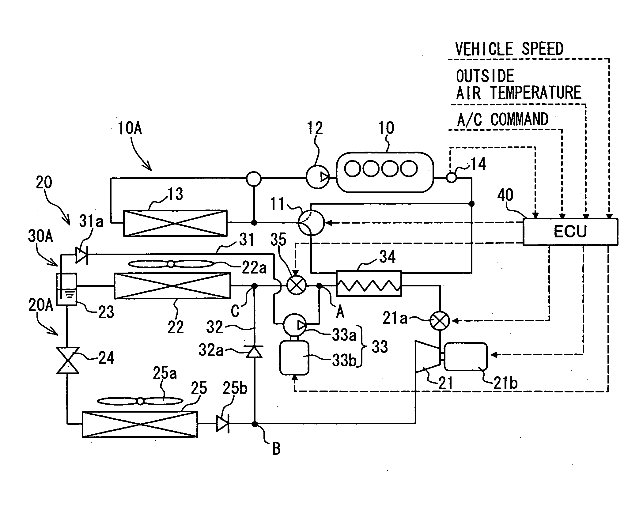
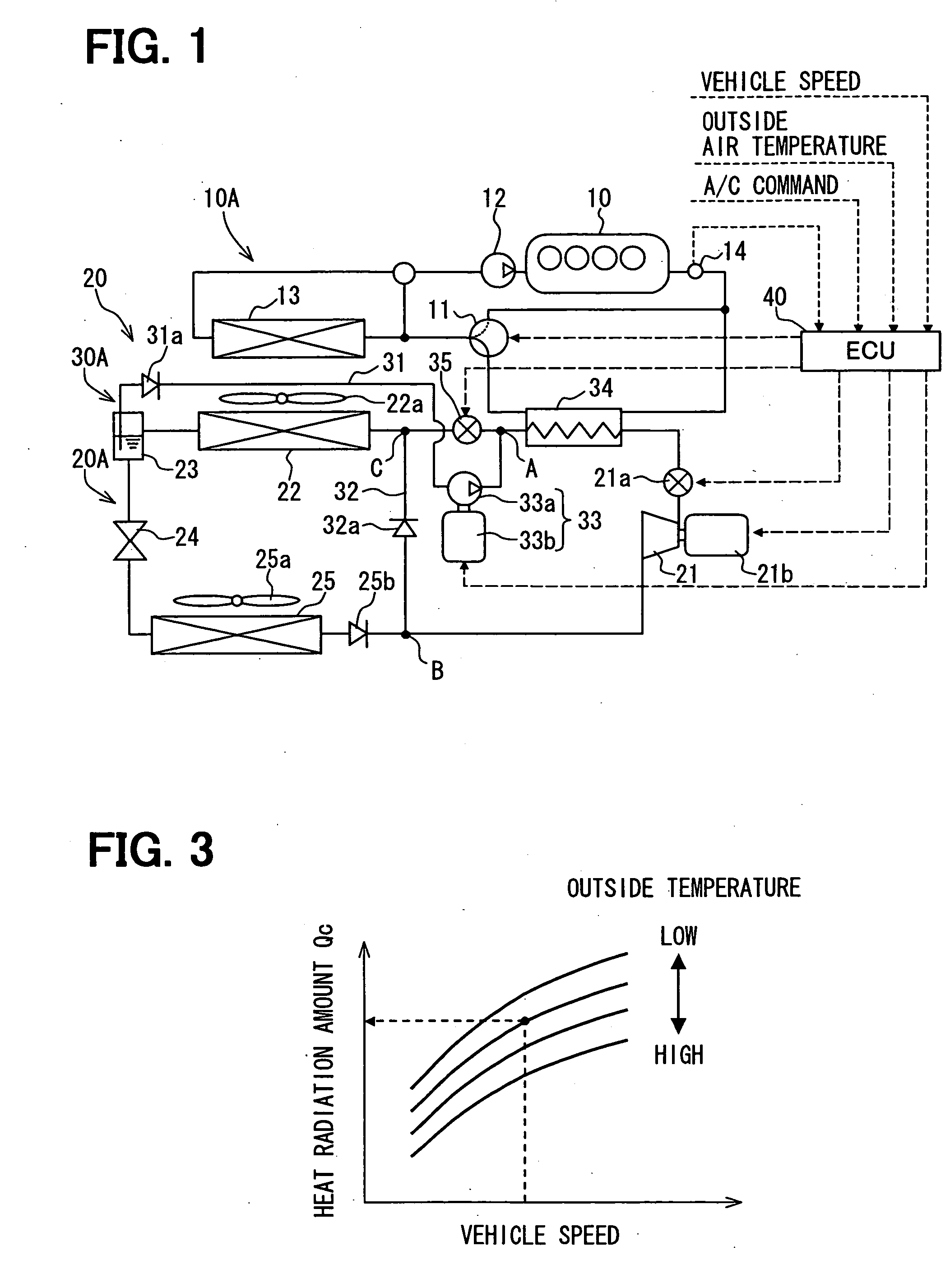
[0032] A first embodiment of the present invention is a waste heat utilization device 20 for utilizing waste heat from a heat engine. The waste heat utilization device 20 is applied to a vehicle having an internal combustion engine 10, which corresponds to the heat engine, as a source of a driving force for a movement of the vehicle. The waste heat utilization device 20 collects energy from the waste heat generated by the engine 10 and has a Rankine cycle 30A and a controller 40. The Rankine cycle 30A commonly uses some devices constituting a refrigerating cycle 20A. Hereafter, a system structure of the waste heat utilization device 20 is described with reference to FIG. 1.
[0033] The refrigerating cycle 20A utilizes low temperature heat and high temperature heat for air conditioning by transferring heat from a low temperature side to a high temperature side, and has an expansion-compressor device 21, a condenser device 22, a gas-liquid separator 23, a depressurizing device 24, and ...
second embodiment
[0080] A second embodiment of the present invention is described with reference to FIGS. 9 to 11. In the second embodiment, a method of calculating (determining) the optimum heat collection amount Qho is different from that of the first embodiment.
[0081] As shown in FIG. 9, a pressure sensor 22b is provided at a gas-liquid separator side (i.e. an outlet side) of the condenser device 22, to detect a condenser side pressure Pc and to output to the controller 40 a pressure signal indicating the detected condenser side pressure Pc. The input of the outside air temperature signal and the vehicle speed signal to the controller 40 is omitted in this embodiment.
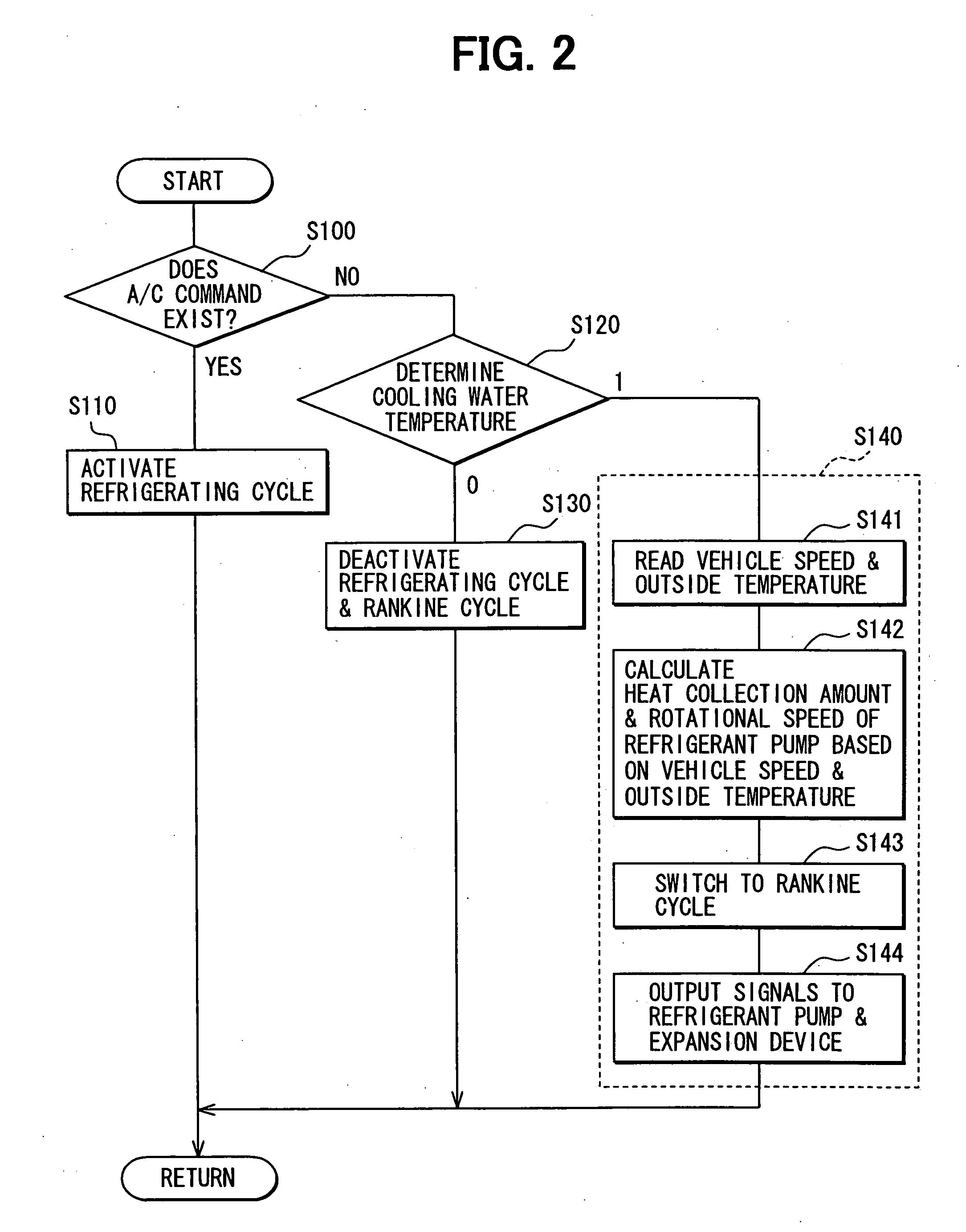
[0082] In addition, as shown in FIG. 10, the step S140 for the operation of the Rankine cycle 30A is replaced with a step S140A, which is the same as the step S140 except for the steps S141 and S142 which are replaced with steps S141A and S142A.
[0083] The operation of the controller 40 is described by focusing on modifications des...
third embodiment
[0086] A third embodiment of the present invention is described with reference to FIGS. 12 and 13. The third embodiment is different from the first embodiment in that the controller 40 controls the flow amount G of the refrigerant in a different way.
[0087] In this embodiment, as shown in FIG. 12, a bypass passage 36 bypassing the refrigerant pump 33 and a flow amount controlling valve 36a changing a cross section of the bypass passage 36 are provided. A degree of an opening of the flow amount controlling valve 36a is controlled by the controller 40.
[0088] In addition, as shown in FIG. 13, the step S140 for the operation of the Rankine cycle 30A is replaced with a step S140B, which is the same as the step S140 except for the steps S142 and S144 which are replaced with steps S142B and S144B.
[0089] The operation of the controller 40 is described by focusing on modifications described above. When the controller 40 determines at the step S120 that the cooling water temperature is high...
PUM
 Abstract
Description
Claims
Application Information