
Method for dispensing an energy reactive adhesive

a technology dispensing methods, which is applied in the direction of adhesive processes, packaging, lamination ancillary operations, etc., can solve the problems of adhesive placement, conventional adhesives may damage the package surface upon separation, and subsequent de-unitization of substrates, so as to reduce the temporary bonding characteristics of light reactive adhesives, the ability of energy reactive adhesives to be exposed, and the effect of reducing the bonding capacity

Inactive Publication Date: 2006-10-12
NORDSON CORP
View PDF18 Cites 6 Cited by
  • Summary
  • Abstract
  • Description
  • Claims
  • Application Information

AI Technical Summary

Benefits of technology

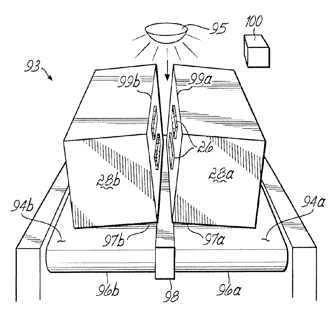
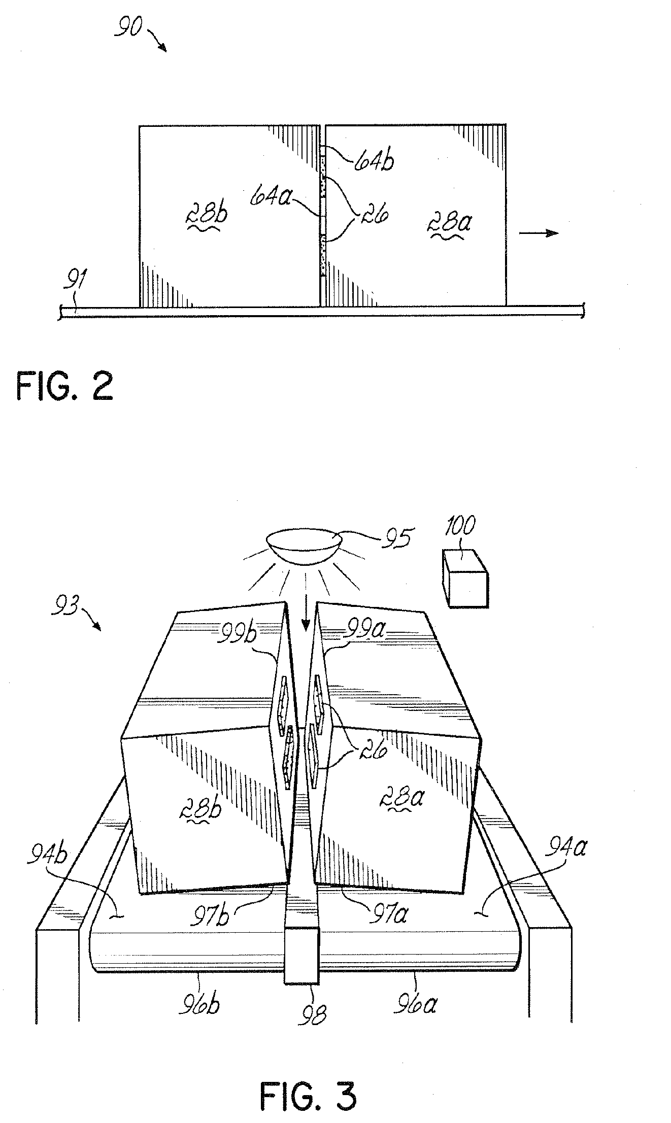
[0006] The bonding capability of the energy reactive adhesive is reduced when exposed to a source for radiating energy within the electromagnetic spectrum, excluding infrared radiation. A typical source for radiating energy radiates ultraviolet light. The reactive adhesive is exposed to the source for radiating energy when de-unitized. To this end, a mechanical arm may be used to separate the first and second surfaces in order to better expose the energy reactive adhesive to the source for radiating energy. The radiation exposure causes the temporary bonding characteristics of the light reactive adhesive to be reduced, so that a package, bag, carton, box or other container, and / or a pallet or other substrate may consequently be easily separated without tearing or defacing their outer surfaces. As such, substrates are economically and efficiently unitized and de-unitized in a manner that mitigates or eliminates residue and surface damage.

Problems solved by technology

While these materials and their associated application processes generally succeed in securing packages to each other and / or a pallet, the subsequent de-unitizing of the substrates can be problematic.
For example, conventional adhesives may damage package surfaces upon separation.
Adhesive placement and tackiness often makes carton removal from a pallet difficult, requiring exertion and / or tools, such as shears or a crowbar.
Such separation practices can damage graphics and compromise package integrity.

Method used


Image

  • Method for dispensing an energy reactive adhesive
  • Method for dispensing an energy reactive adhesive
  • Method for dispensing an energy reactive adhesive

Examples


Embodiment Construction

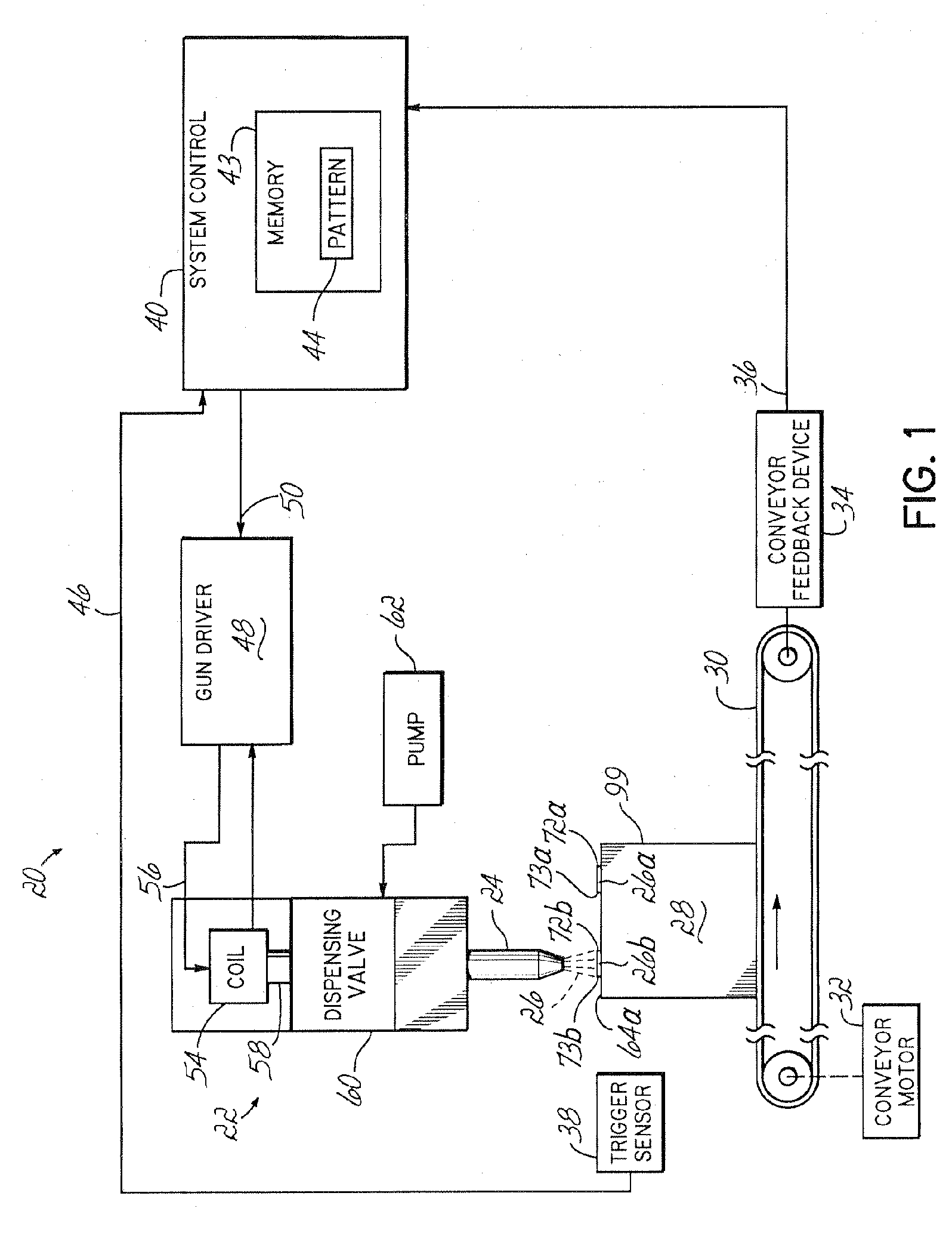
[0012]FIG. 1 shows a block diagram of a fluid dispensing system 20 configured to facilitate unitization by applying an energy reactive bonding agent, or adhesive 26, to cartons or other substrate surfaces 64a. A suitable energy reactive adhesive 26 comprises a material whose bonding properties, e.g., tackiness, are reduced when exposed to a source that radiates energy in one or more spectrums of the electromagnetic spectrum, excluding infrared radiation, i.e., heat. For instance, the energy reactive adhesive 26 typically comprises a thermoplastic material that is tacky under ambient conditions and that becomes brittle when subject to a radiating energy source. That is, the tackiness of the energy reactive adhesive 26 is reduced when exposed to the source that radiates energy. In one preferred embodiment, the radiating energy source includes an ultraviolet light source.

[0013] The system 20 applies the energy reactive adhesive 26 on and / or between substrate surfaces, and upon setting...


PUM

PropertyMeasurementUnit
Wavelengthaaaaaaaaaa
Temperatureaaaaaaaaaa
Energyaaaaaaaaaa

Abstract

A method uses energy reactive adhesive to temporarily unitize packages. Particular placement of the reactive adhesive allows the packages to be bonded until exposure to ultraviolet light or other radiated energy having a wavelength of less than about 700 nanometers causes a photoinitiator or other catalyst in the reactive adhesive to reduce the temporary bond. Once the bond has reduced, the packages may be easily separated for stocking with minimal adhesive residue.

Description

FIELD OF THE INVENTION [0001] The present invention generally relates to an adhesive dispensing system, and more particularly, to an adhesive dispensing system for temporarily unitizing substrate surfaces. BACKGROUND OF THE INVENTION [0002] When cartons, packages or bags are adjacently stacked, it is often desirable that the items remain temporarily in a stable group, or unitized. Unitization is particularly advantageous in the context of warehousing, palletizing and transportation operations. For example, large numbers of packages may be piled onto wooden pallets and moved from different locations on forklifts. The pallets are raised on elevators for warehouse storage, or for long distance transport. When the stored item is actually used, the cartons are de-unitized, or separated, so that a single package can be picked up and carried, for example, by a plant operator. [0003] Conventional materials used to unitize package, bag, pallet and other substrate surfaces include tape, glues...

Claims


Application Information

Patent Timeline
IPC IPC(8): B32B37/00
CPCB29C65/1403B29C65/485B29C65/1409B29C65/1432B29C65/4845B29C65/76B29C66/1142B29C66/20B29C66/43B65B17/02C09J5/00C09J5/06C09J2205/302B29C65/1406B29C65/4825B29C65/4815B29C65/524B29C65/1483B29C65/00B29C66/21C09J2301/502
Inventor SAIDMAN, LAURENCE B.RATERMAN, JOHN M.ANIS, KHALED
Owner NORDSON CORP
Learn More