
Method and conduit for transmitting signals

Active Publication Date: 2006-10-12
SCHLUMBERGER TECH CORP
View PDF48 Cites 154 Cited by
  • Summary
  • Abstract
  • Description
  • Claims
  • Application Information

AI Technical Summary

Benefits of technology

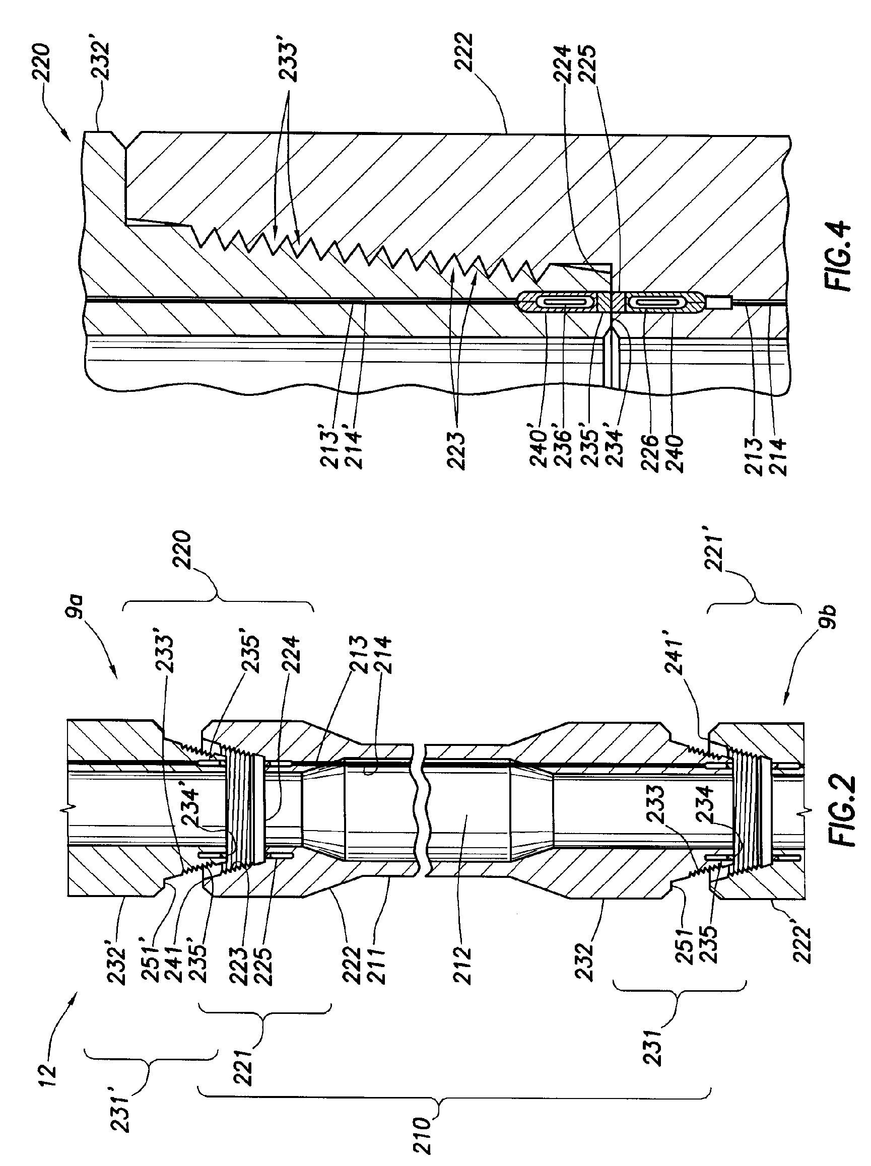
[0037] In a further aspect, the present invention provides a method for transmitting signals along the length of a tubular body. The tubular body is equipped with a communicative coupler at or near each of its two ends, with each of the communicative couplers comprising a coil having two or more independent coil windings. Two or more conductors are extended independently along or through the wall of the tubular body, and the independent conductors are connected between the respective independent coil windings so as to establish two or more independently-wired links. Accordingly, wired communication may be maintained when a failure occurs in one (or possibly more) of the wired links.

Problems solved by technology

Such slow rates are incapable of transmitting the large amounts of data that are typically gathered with an LWD string.
Additionally, in some cases (e.g., when using foamed drilling fluid), mud-pulse telemetry does not work at all.
This delay significantly reduces the value of the data for real-time or near real-time applications.
Also, there is a significant risk of data loss, for example, if the MWD / LWD tool(s) are lost in the borehole.
Electromagnetic (EM) telemetry via subsurface earth pathways has been tried with limited success.
The utility of EM telemetry is also depth-limited, depending on the resistivity of the earth, even at low data transmission rates.
Acoustic telemetry through the drill pipe itself has been studied extensively but has not been used commercially to date.
In theory, data transmission rates in the 10's of bits / second should be possible using acoustic waves conveyed through the steel drill string, but this has not been reliably proven.

Method used


Image

  • Method and conduit for transmitting signals
  • Method and conduit for transmitting signals
  • Method and conduit for transmitting signals

Examples


Embodiment Construction

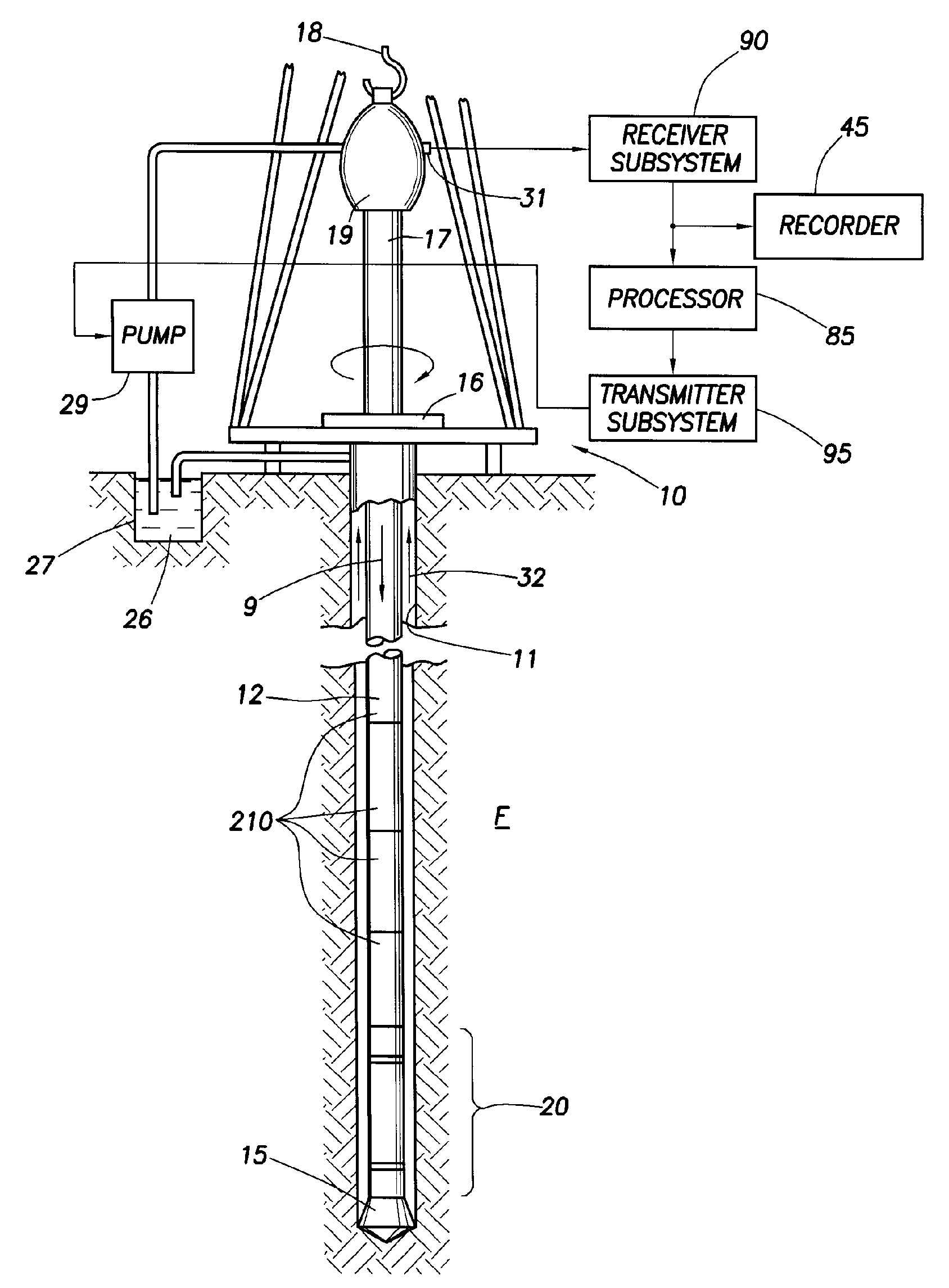
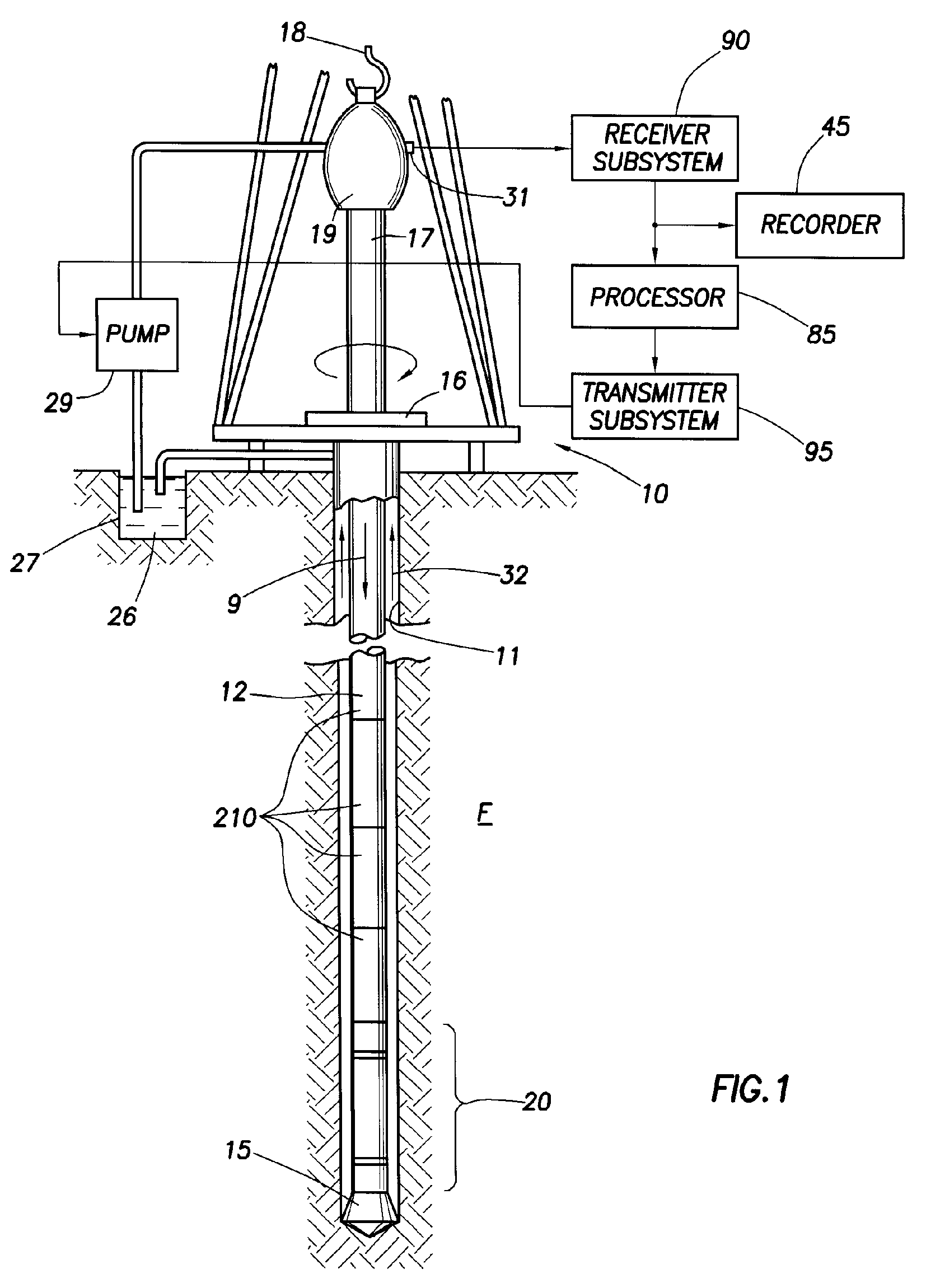
[0065]FIG. 1 illustrates a conventional drilling rig and drill string in which the present invention can be utilized to advantage. As shown in FIG. 1, a platform and derrick assembly 10 is positioned over a borehole 11 penetrating a subsurface formation F. A drill string 12 is suspended within the borehole 11 and includes a drill bit 15 at its lower end. The drill string 12 is rotated by a rotary table 16, energized by means not shown, which engages a kelly 17 at the upper end of the drill string. The drill string 12 is suspended from a hook 18, attached to a traveling block (not shown), through the kelly 17 and a rotary swivel 19 which permits rotation of the drill string relative to the hook.

[0066] Drilling fluid or mud 26 is stored in a pit 27 formed at the well site. A mud pump 29 delivers drilling fluid 26 to the interior of the drill string 12 via a port (not numbered) in the swivel 19, inducing the drilling fluid to flow downwardly through the drill string 12 as indicated by...


PUM

PropertyMeasurementUnit
Angleaaaaaaaaaa
Angleaaaaaaaaaa
Lengthaaaaaaaaaa

Abstract

An expandable tubular sleeve having utility for lining a downhole tubular member includes a tubular body having a portion that is predisposed to initiate expansion thereof under the application of internal fluid pressure. The predisposed portion of the body may be a plastically-deformed portion formed, e.g., by application of mechanical force to a wall of the body. The predisposed portion of the body may be defined by a portion of the body having reduced wall thickness. The reduced wall thickness may be achieved, e.g., by reinforcing the wall thickness everywhere except the predisposed portion. The predisposed portion of the body may be formed by modifying the material properties of the body, e.g., by localized heat treatment. The sleeve and related apparatuses and methods are useful for securing and protecting a cable having one or more insulated conductive wires for transmission of signals between locations downhole and at the surface.

Description

BACKGROUND OF THE INVENTION [0001] 1. Field of the Invention [0002] The present invention relates to downhole telemetry systems, and more particularly to wired conduit such as drill pipe that is adapted for conveying data and / or power between one or more downhole locations within a borehole and the surface. [0003] 2. Background of the Related Art [0004] Measurement While Drilling (MWD) and Logging While Drilling (LWD) systems derive much of their value from the ability to provide real-time information about downhole conditions near the drill bit. Oil companies use these downhole measurements to make decisions during the drilling process, e.g., to provide input or feedback information for sophisticated drilling techniques such as the GeoSteering system developed by Schlumberger. Such techniques rely heavily on instantaneous knowledge of the formation that is being drilled. Accordingly, the industry continues to develop new real-time (or near real-time) measurements for MWD / LWD, inclu...

Claims


Application Information

Patent Timeline
IPC IPC(8): E21B17/00E21B47/00
CPCB21D39/04E21B17/003E21B43/108E21B43/103E21B43/106E21B17/028E21B17/0283E21B47/12
Inventor MADHAVAN, RAGHUBOYLE, BRUCE W.CLARK, BRIAN
Owner SCHLUMBERGER TECH CORP
Learn More