Welding torch with enhanced cooling

a technology of welding torch and cooling element, which is applied in the direction of cooling electrode holders, electrode supporting devices, manufacturing tools, etc., can solve the problems of negative impact on the performance and life of welding devices, degradation of conductors and conductive elements within welding torch, unwanted and undesirable consequences, etc., to increase the surface area of the hollow member, improve the cooling effect, and improve the effect of cooling

Inactive Publication Date: 2006-10-12
ILLINOIS TOOL WORKS INC
View PDF5 Cites 19 Cited by
  • Summary
  • Abstract
  • Description
  • Claims
  • Application Information

AI Technical Summary

Benefits of technology

[0006] In accordance with one exemplary embodiment, the present invention provides a welding torch that presents beneficial cooling properties. To increase the efficacy of cooling, the exemplary welding torch includes a hollow member that has a plurality of protrusions that at least partially define passageways that generally extend in the direction of the hollow member's longitudinal axis. Advantageously, these protrusions increase the surface area of the hollow member, providing a larger area through which heat developed in the welding torch may be dissipated. Additionally, in the event that a shielding gas is employed, the shielding gas can be routed through the passageways, further increasing the efficacy of cooling within the welding torch.
[0007] As another exemplary embodiment, the present inventi...

Problems solved by technology

Unfortunately, such unwanted heating can negatively impact the performance and life span of the welding device.
For example, resistive heating can lead to the degradation of the conducto...

Method used


Image

  • Welding torch with enhanced cooling
  • Welding torch with enhanced cooling
  • Welding torch with enhanced cooling

Examples


Embodiment Construction

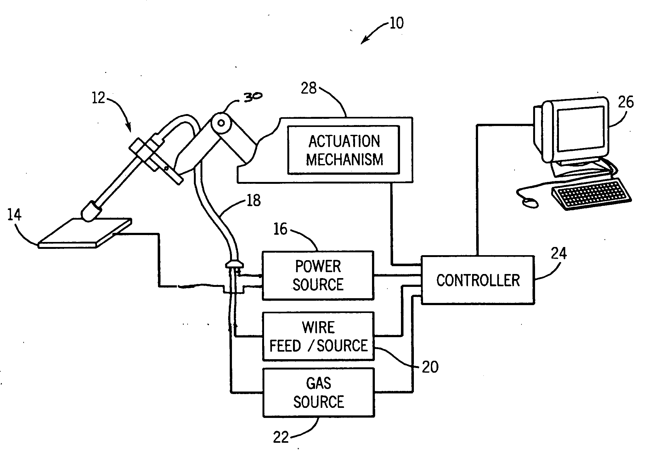
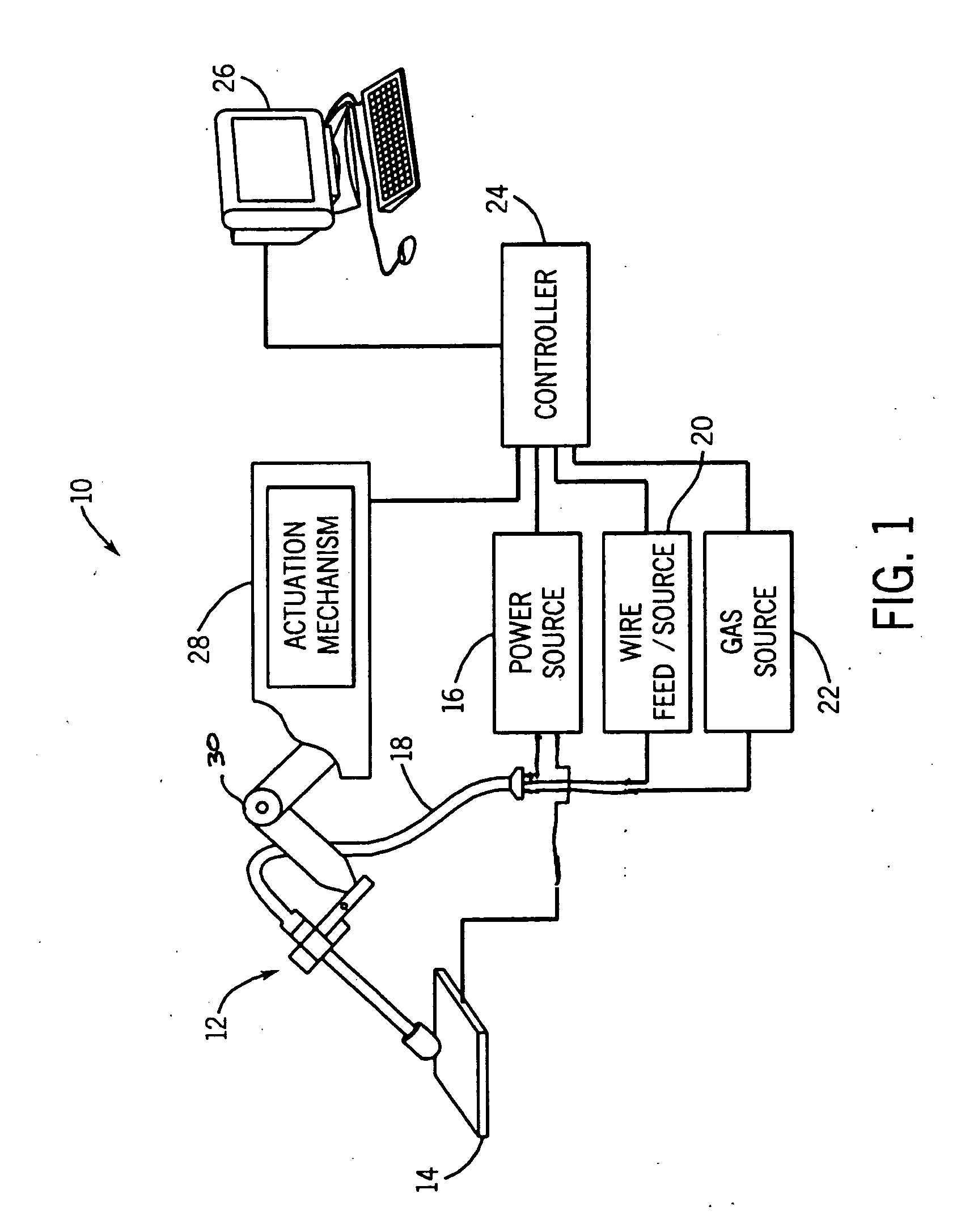
[0014] Turning to the figures, FIG. 1 illustrates an exemplary gas shielded and wire-feed robotic welding system 10. Prior to continuing, however, it is worth noting that the following discussion merely relates to exemplary embodiments of the present invention. As such, the appended claims should not be viewed as limited to those embodiments discussed herein. Indeed, the present invention provides benefits to both robotic and non-robotic welding systems as well as to both shielded and non-shielded welding devices. In summary, the prevention invention, which, in a general sense, relates to improved cooling and flow apparatus and methods, is applicable to a vast number of welding systems and devices, for instance.

[0015] Returning to the exemplary welding system 10, it includes a welding torch 12 that defines the location of the welding operation with respect to a workpiece 14. Specifically, placement of the welding torch 12 at a location proximate to the workpiece 14 allows current, ...


PUM

PropertyMeasurementUnit
Lengthaaaaaaaaaa
Dielectric polarization enthalpyaaaaaaaaaa
Diameteraaaaaaaaaa

Abstract

In accordance with one embodiment, the present invention relates to a welding torch. The welding torch includes a first hollow member through which wire electrode is routed and that has a plurality of protrusions that extend from an inner surface thereof. Advantageously, these protrusions of the exemplary welding torch increase the surface area of the first hollow member, and increasing the surface area improves the ability of the welding torch to dissipate heat to the surrounding environment, for instance.

Description

BACKGROUND [0001] The present invention relates generally to welding devices and, more specifically, to apparatus and methods for cooling welding torches. [0002] A common metal welding technique employs the heat generated by electrical arcing to transition workpieces to a molten state. One technique that employs this arcing principle is wire-feed welding. At its essence, wire-feed welding involves routing current from a power source and into an electrode that is brought into close proximity with the workpieces. When close enough, current arcs from the electrode to the workpieces, completing a circuit and generating sufficient heat to weld the workpieces to one another. Often, the electrode is consumed and becomes part of the weld itself. [0003] To prevent the ingress of impurities into the molten weld, a flow of shielding material is typically provided around the weld location. By way of example, inert shielding gas is routed from a gas source and through the welding cable, and, at ...

Claims


Application Information

Patent Timeline
IPC IPC(8): B23K9/173
CPCB23K9/285
Inventor GIESE, WILLIAM R.
Owner ILLINOIS TOOL WORKS INC
Why Eureka
Try Eureka