Computer mouse for harsh environments and method of fabrication

a computer mouse and harsh environment technology, applied in computing, instruments, electric digital data processing, etc., can solve the problems of inability to provide speed and precision control, device failure, and inability to accurately control the pointing operation, etc., to achieve the effect of reducing or substantially eliminating the potential buildup of residu

Inactive Publication Date: 2006-10-12
IKEY
View PDF71 Cites 18 Cited by
  • Summary
  • Abstract
  • Description
  • Claims
  • Application Information

AI Technical Summary

Benefits of technology

[0014] Still another object of the present invention is to provide a rugged computer mouse that may be manufactured with a minimal variation in the manufacturing processes presently employed by the computer industry.
[0016] The present invention may further provide an opening within the pliable cover for receiving a communications cable connecting between the mouse control circuit and an associated computer. The opening and communications cable associate so as to form a generally impenetrable seal protecting the mouse control circuit from a harsh environment. Moreover, the base may include transparent lens for communicating optical signals from the movement sensor and circuitry. The lens is formed so as to minimize or substantially eliminate the potential buildup of residue from the harsh environment.
[0017] The present invention, therefore, provides a rugged computer mouse for use with a computer in a waterproof and sealed structure that is chemical resistant. Moreover, the present invention provides these advantages without the need for a specially-designed rubber molding that occurs only through the use of an additional complicated manufacturing process. The rugged computer mouse of the present embodiment may be washed down with water or sterilized with disinfectant without damage and provides an attractive pointing device for use with a computer in harsh industrial environments, hospital and health care institutions, laboratory situations and food service and manufacturing applications.

Problems solved by technology

This includes harsh environments that may include dampness, wetness, damaging gases, heavy particulate matter and other types of environments.
Within these environments, such pointing devices may be or become inoperative due to such environmental the environment constituents entering their mechanical, electrical, and electronic portions.
Problems with the various different types of pointer devices presently available for harsh environments include the fact that users expect to use a device that is in form and function similar to a standard computer mouse.
When new users attempt to operate pointing devices other than a standard mouse, inevitably inaccuracies and mistakes often occur in the control of the pointing operation.
Such devices attempt, but fail, to provide both speed and precision control until the user masters the operation of the new and different device.
While computer device designers have attempted to produce a mouse pointing device for use in harsh environments, none has yet overcome the problems of protecting the mouse circuitry without presenting to the user a still different or awkward device.
Unfortunately, today's computer mouse for harsh environment include none of these ergonomic improvements.
Moreover, the few harsh environment or rugged computer mouse designs that do exist still fail to take into considerations the manufacturing improvements that have arisen over the years to produce such devices.
For example, rugged computer mouse designs use a fully encapsulating cover that includes complicated manufacturing and design process such as requiring that a protective covering be molded to the mouse base.
Such considerations add, unnecessarily, to the manufacturing costs of such devices.

Method used


Image

  • Computer mouse for harsh environments and method of fabrication
  • Computer mouse for harsh environments and method of fabrication
  • Computer mouse for harsh environments and method of fabrication

Examples


Embodiment Construction

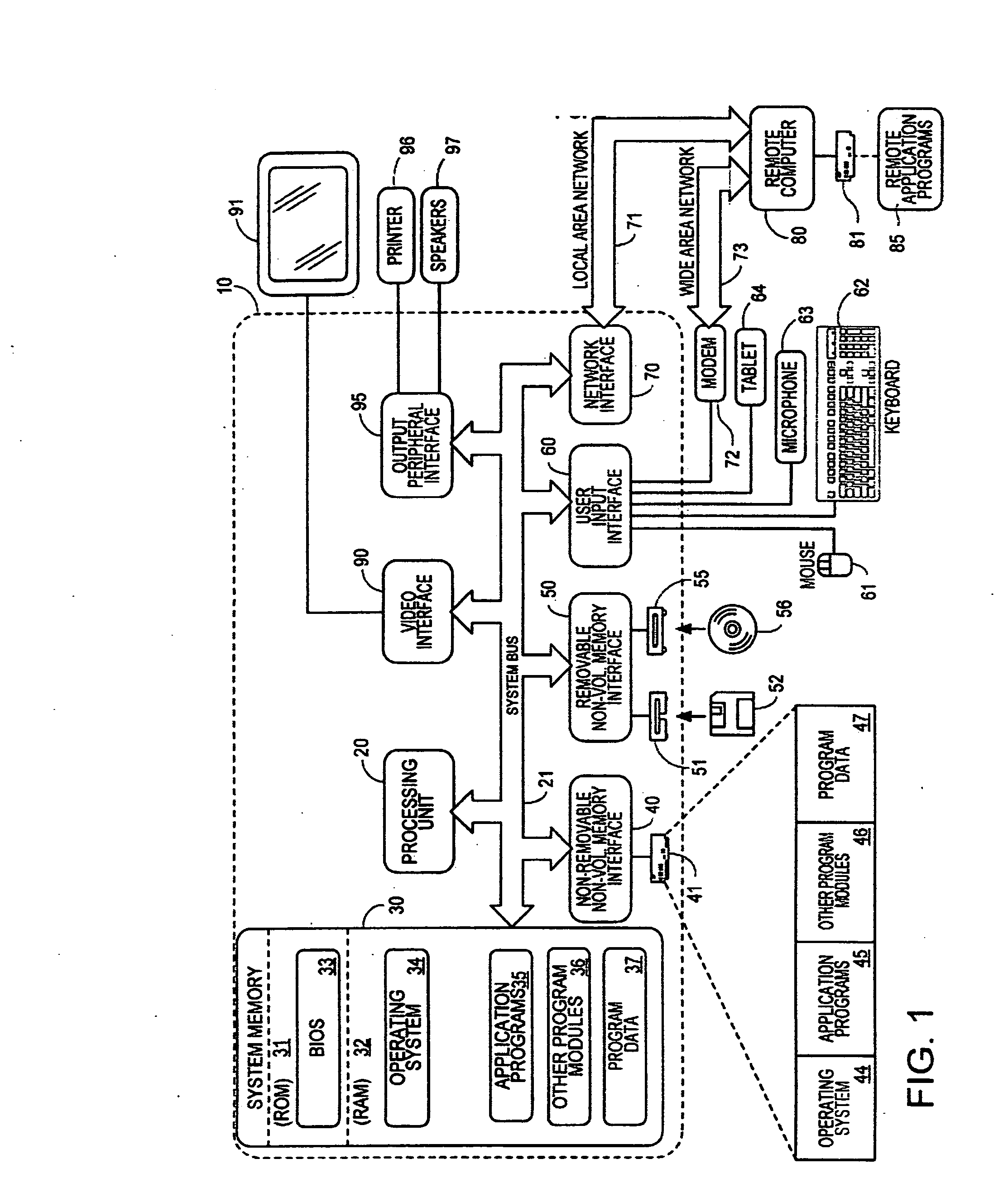
[0041] Although described with particular reference to a personal computer, the claimed subject matter can be implemented in any information technology system in which it is necessary or desirable to achieve rapid and efficient use of memory resources during processing operations.

[0042] Those with skill in the computing arts will recognize that the disclosed embodiments have relevance to a wide variety of computing environments in addition to those specific examples described below. In addition, the methods of the disclosed invention can be implemented in software, hardware, or a combination of software and hardware. The hardware portion may be implemented using specialized logic; the software portion can be stored in a memory and executed by a suitable instruction execution system such as a microprocessor, personal computer or mainframe.

[0043] All references, including publications, patent applications, and patents, cited herein are hereby incorporated by reference to the same ex...


PUM


Abstract

A rugged computer mouse for use in a harsh liquid, chemical or gaseous environment, includes a pliable cover formed as a single unit that forms a generally impenetrable surface having a seal edge. The seal edge includes a trench. The surface has formed thereon at least one mouse control button region corresponding to a location of a pressure sensitive mouse control button. An ergonomically formed frame provides structural support and includes at least one pressure sensitive mouse button, which the mouse control button region covers. A mouse control circuit resides beneath the ergonomically formed frame and includes a mouse control button circuit that is responsive to pressure applied to the pressure sensitive mouse button. The mouse control circuit also includes a movement sensor and circuitry for relating the position of the computer mouse to the position of the graphical pointer. A base securely receives the mouse control circuit, the frame, and the pliable cover and comprises a ridge. The ridge inserts into the trough of the pliable cover and together with the pliable cover forms a generally impenetrable casing surrounding the frame, and the mouse control circuit.

Description

FIELD OF THE INVENTION [0001] This invention pertains to computer systems and, more particularly, to a pointer device, commonly referred to as a mouse, which is used to control a visual pointer on a display of a computer system. BACKGROUND OF THE INVENTION [0002] A computer system includes many components, such as the central processing unit (or processor); temporary memory for storing program instructions (like random access memory, or RAM); a permanent storage device (such as a hard disk); and a variety of user interface devices, such as a video display, a keyboard, and a pointing device which controls the movement of a graphical pointer on the display. The graphical pointer permits selecting certain areas on the screen, such as words in a text-only display or icons in a more complicated graphical user interface (GUI). The user selects an area by placing the graphical pointer over the area (i.e., moving the physical pointing device) and then clicking one or more buttons on the poi...

Claims


Application Information

Patent Timeline
Patent Type & Authority Applications(United States)
IPC IPC(8): G09G5/08
CPCG06F3/03543
Inventor MEYER, STEVEN H.EAST, JOEL A.FUSELIER, KENNETH A.
Owner IKEY
Why Eureka
Try Eureka