Layered structure with printed elements

Inactive Publication Date: 2006-10-12
AVESO INC
View PDF49 Cites 107 Cited by
  • Summary
  • Abstract
  • Description
  • Claims
  • Application Information

AI Technical Summary

Benefits of technology

[0017] The present invention involves a thin, layered structure for providing a laminated unit that contains a variety of electronic components. The present invention may be used to produce efficiently an electronic core structure that provides specified electronic functionality of a variety of financial card and other applications, that has the required structural integrity, and that permits finishing layers to be applied while

Problems solved by technology

Other processes such as cold lamination, which relies on adhesive bonding, have been developed but have been implemented on a limited basis.
Incorporating electronic components prior to hot lamination, such as integrated circuits (ICs), antennas, batteries, displays, switches and other circuitry, presents significant difficulty when the hot lamination process is done.
The primary difficulty results from the various heights of the different components and the various heat transfer characteristics of the materials employed.
Unless these are adequately addressed, performing the hot lamination process with electronic components in place in the layers to be laminated will result in surface defects, unacceptable warping or damage to the internal components.
However, more complex structures make it more difficult to yield acceptable results, due to the number and size of the components and the need to meet visual and ISO quality standards.
This approach is relatively slow and does not yield a cost-effective, high volume manufacturing process relative to a simple lamination process.
This approach is difficult to implement in high volume due to the inherent variability in raw materials and requires additional steps in the manufacturing process, going beyond lamination, to achieve the desired results.
The use

Method used


Image

  • Layered structure with printed elements
  • Layered structure with printed elements
  • Layered structure with printed elements

Examples


example 1

Discrete Component Placement and Multilayered Circuit

[0121] Consistent with the teachings above, the invention will now be illustrated in a construction with two composite layers, a base layer 220 and cover layer 210, shown in FIG. 6, which are then laminated together to form the core electronic structure.

[0122] The electronic core is constructed by placing the necessary components on a base sheet 150 in the proper configuration for the part layout. The base sheet may be PVC or other film which will laminate to outside layers through the hot lamination process. The thickness of the base sheet will preferably be in the range of 0.001 to 0.005 inches with a preferred thickness of 0.002 inches. The various components are held in place with a thin layer of pressure sensitive adhesive.

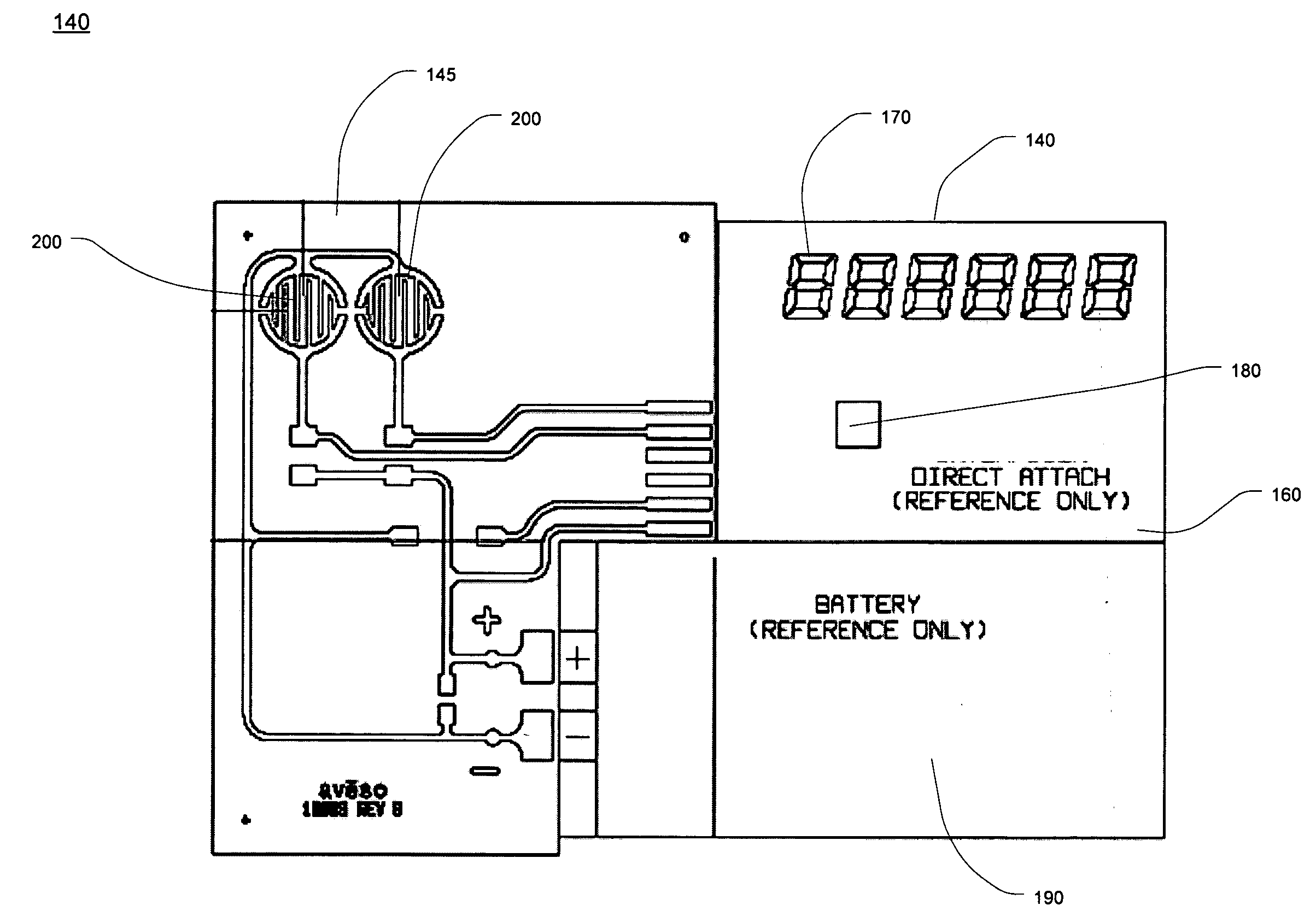
[0123] The components placed on the base sheet 150 include membrane switch domes, the battery and display cell. The initial component placement determines the spacing of the relief areas as well as the v...

example 2

Planar Circuit and Electrical Connects

[0130] In another example, the construction of base layer 220 is modified by printing the entire connecting circuit on the top of the structure which will match up with the connection points of the display cell and battery components and contain the base for the switches. Electrical connection between the connecting circuit and the components is then provided through needle dispensing to provide a conductive path to each connection. The remaining structure remains the same as Example 1.

[0131] Examples 1 and 2 illustrate the inherent flexibility of printing circuitry within the electronic core. The electronic core will typically have 5-7 discrete surfaces to print circuit elements prior to final assembly. This embodiment of the invention provides the capability to layer the circuitry within the core and use all available surfaces to fit the necessary circuits. This is useful when elaborate circuits must be contained within the area available fo...

example 3

Embedded Carbon / Zinc Battery

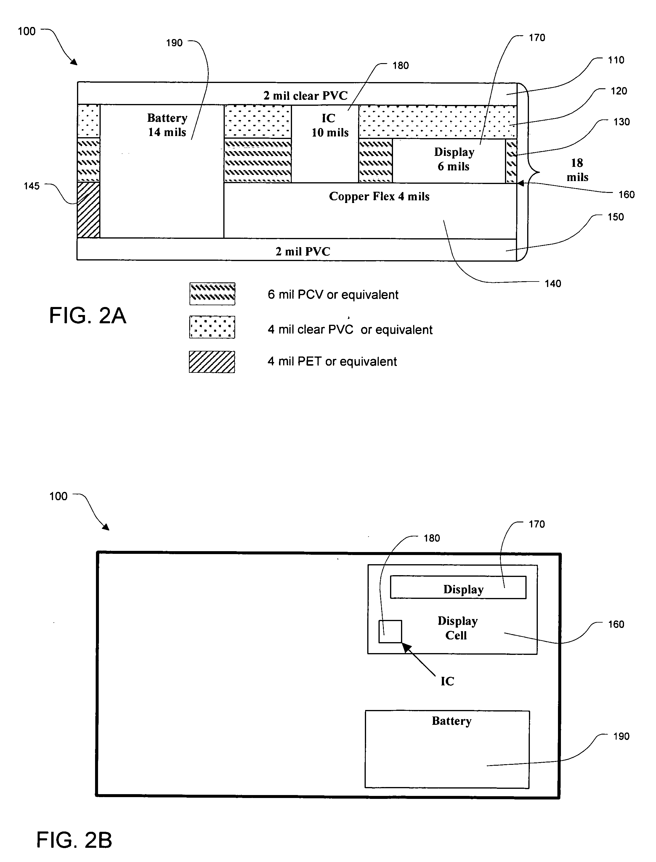
[0133] As described, batteries suitable for use in a smart card are typically 0.012 to 0.016 inches in total thickness. Of that total thickness, 0.006 to 0.010 inches are comprised of packaging films to seal the battery. This example illustrates the use of core layers as part of the battery packaging which saves overall thickness and complexity of the core.

[0134] This construction is based on the base layer 220 / cover layer 210 as described in Example 1. On the base layer, the battery anodes and current collectors are deposited on the top of the second film PVC layer 150. Separately, on the same layer, the cathodes and current collectors are printed as well. The total thickness of the battery layers is 0.006 inches which matches the height of the display. Two separate cells are required to achieve the required 3V from the system. The attach circuitry connects the batteries in series to the other elements.

[0135] The cover layer 210 is constructed to have...


PUM

PropertyMeasurementUnit
Thicknessaaaaaaaaaa
Dielectric polarization enthalpyaaaaaaaaaa
Volumeaaaaaaaaaa

Abstract

The present invention incorporates electronic components into an electronic core structure that may be readily hot laminated by existing processes. The structure may include multiple desired electronic components, such as a display, battery or other power source, integrated circuits, switches, magnetic stripe emulator, antenna, smart chips or other input devices. The structure includes laminated buffer layers to bridge layers and compensate for variation in electronic component dimensions. The structure may also incorporate battery packaging as part of the core layer structure and use printed electronic circuitry as part of the electronic core layers to impart the desired characteristics. A variety of components may be incorporated in the structure.

Description

CROSS REFERENCE TO RELATED APPLICATIONS [0001] This application claims the benefit of U.S. Provisional Application No. 60 / 670,076, filed Apr. 11, 2005.FIELD OF THE INVENTION [0002] The present invention relates to a thin, layered structure with built-in electronic functionality, for example a display and associated electronics for driving the display. The display and / or other functional elements in the structure are formed by printing processes. BACKGROUND OF THE INVENTION [0003] The plastic laminated card industry has relied on the process of hot lamination to produce credit cards, identification cards, loyalty cards and other flat tokens containing information. This process consists of layering a variety of plastic sheets which have a variety of functions such as opacity, graphics and protective layers into the finished stack. The layers can be opaque or clear and may contain functional elements such as magnetic stripes. Once the desired layers have been assembled, the assembly is...

Claims


Application Information

Patent Timeline
IPC IPC(8): H05K7/06
CPCH01M6/40H01M10/425H05K1/182H05K1/189Y10T428/24926H05K2201/10037H05K2201/10128H05K2203/1311Y10T428/24917H05K3/284Y02E60/10G06K19/077H05K7/06H05K1/18
Inventor PENNAZ, THOMAS J.QUINDLEN, STEPHEN F.SIME, DAVID G.MCDOUGALL, JAMES P.
Owner AVESO INC
Why Eureka
Try Eureka