Packet transmission method and apparatus

a packet and transmission method technology, applied in the field of packet transmission methods and apparatuses, can solve the problems of inefficient use of original transmission speed, and large time occupied by the header transmission, so as to increase the maximum number of simultaneous calls, shorten the time, and increase the transmission rate

Inactive Publication Date: 2006-10-12
NEC CORP
View PDF4 Cites 14 Cited by
  • Summary
  • Abstract
  • Description
  • Claims
  • Application Information

AI Technical Summary

Benefits of technology

[0021] According to the present invention, voice and other small-sized packets can be sorted by transmission rate and can be transmitted at a high transmission rate to destinations capable of communication at such a transmission rate. The effects produced by doing so include the ability to increase the maximum number of simultaneous calls, shorten the time during which the wireless communication medium is occupied, and transmit VoIP data and other data with a short data length in a more efficient manner.

Problems solved by technology

Moreover, in case of a wireless LAN, as defined in IEEE 802.11, the header portion is transmitted at the lowest transmission rate, and, consequently, the proportion of time occupied by the transmission of the header becomes larger than the proportion used for the bit length, thus rendering impossible efficient use of the original transmission speed.
This is extremely inefficient because frames end up being transmitted at 1 Mbps, i.e. the lowest transmission rate, even to terminals capable of transmission at 11 Mbps.

Method used


Image

  • Packet transmission method and apparatus
  • Packet transmission method and apparatus
  • Packet transmission method and apparatus

Examples


first embodiment

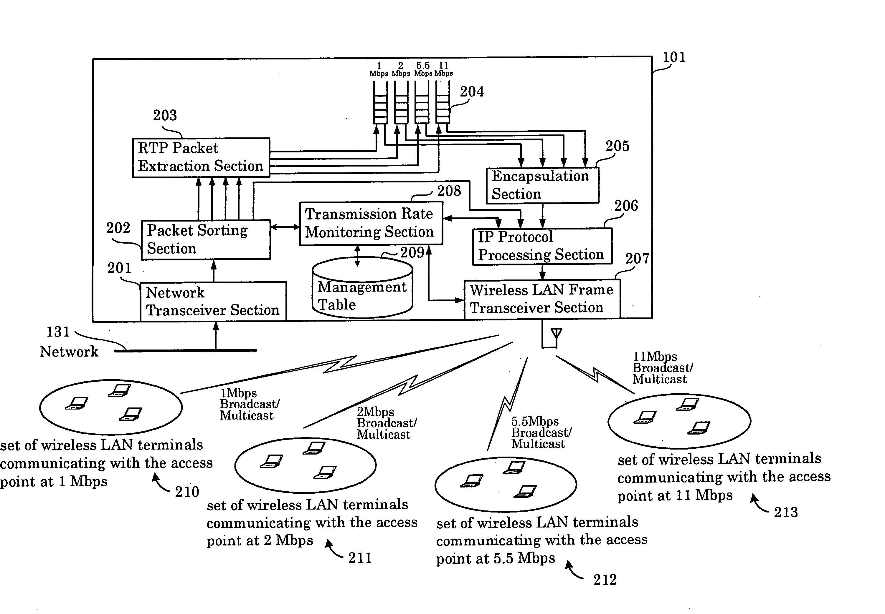
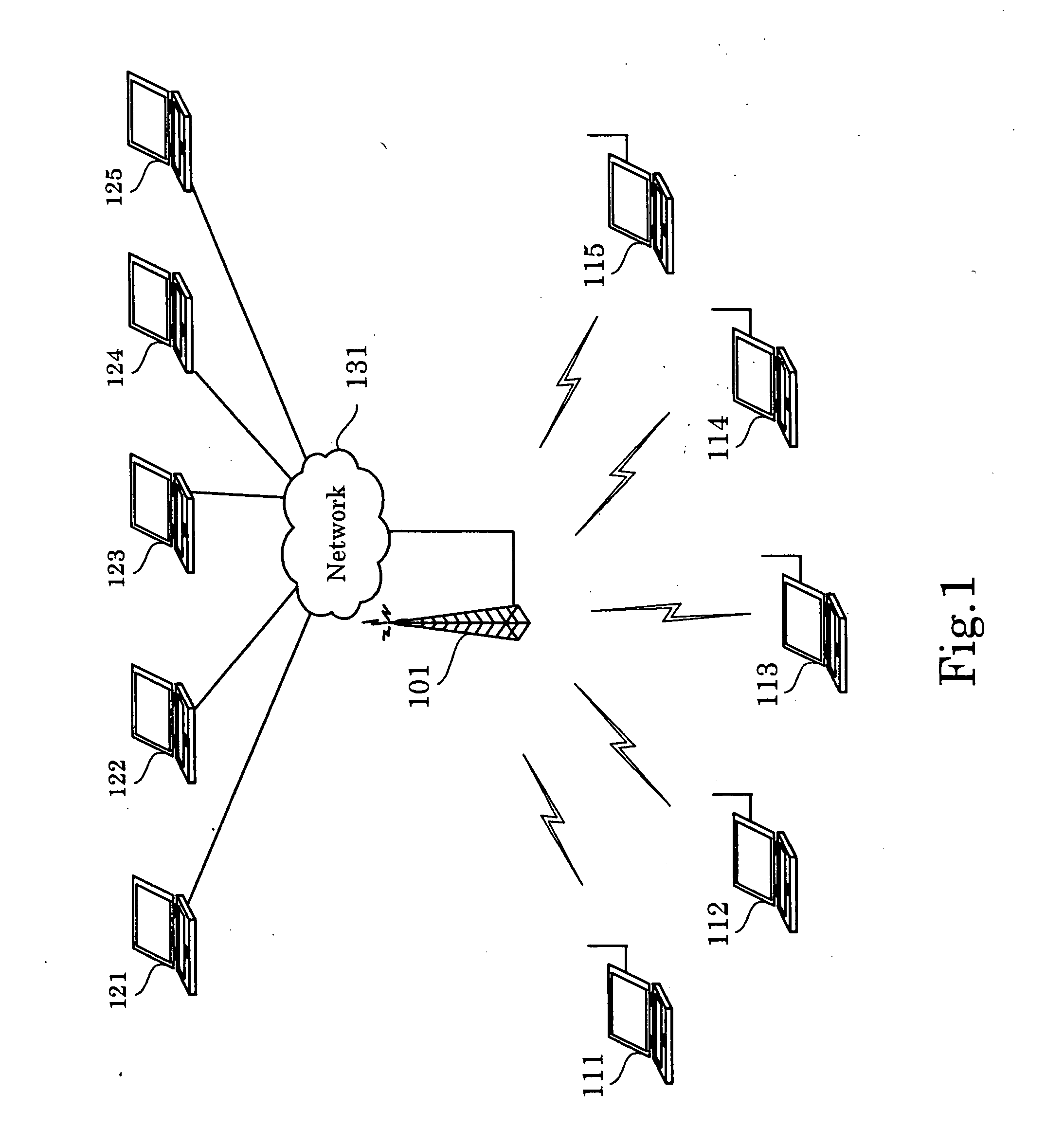
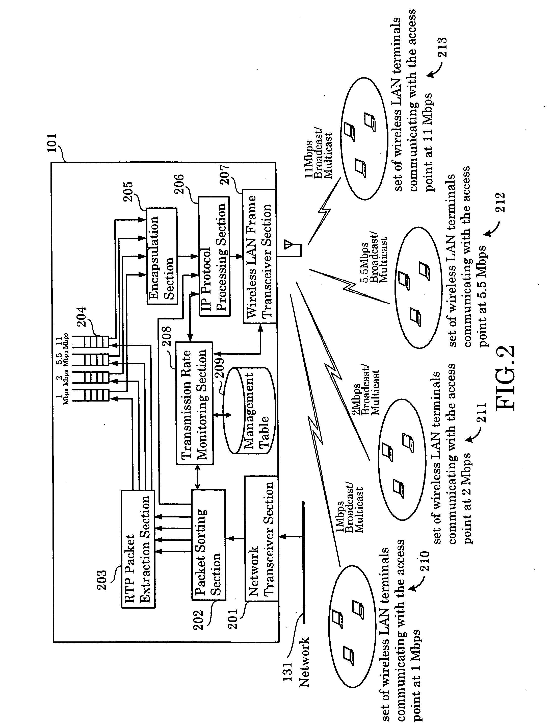
[0038]FIG. 2, which is a block diagram illustrating a first embodiment of the present invention, illustrates an example, in which the packet transmission apparatus of the present invention is implemented as the access point 101 shown in FIG. 1.

[0039] The access point 101 is made up of a network transceiver section 201, a packet sorting section 202, an RTP (Real-time Transport Protocol) packet extraction section 203, encapsulated packet queues 204, an encapsulation section 205, an IP protocol processing section 206, a wireless LAN frame transceiver section 207, a transmission rate monitoring section 208, and a management table 209.

[0040] The network transceiver section 201, which is a protocol processing means located in the physical and data link layer of the OSI 7 layer model, receives data from the network 131 and transmits data to the network 131.

[0041] In addition to IP protocol stack processing, the packet sorting section 202, which is located in the network layer of the OSI...

second embodiment

[0065]FIG. 8, which is a block diagram illustrating a second embodiment of the present invention, illustrates an example, in which the packet transmission apparatus of the present invention is implemented as an access point 101, in the same manner as in the first embodiment.

[0066] The access point 101 is different from the first embodiment in that there is provided a specified rate packet extraction section 214, the packet sorting section 202 does not possess the function of sorting by transmission rate and only sorts packets into packets that should be encapsulated and those that shouldn't, with the encapsulated packet queues 204 storing packets of all transmission rates without pre-processing by transmission rate.

[0067] Next, the operation of the present embodiment is explained with reference to the flow chart of FIG. 9. In the present embodiment, the packet sorting section 202 classifies packets into two types only, i.e. packets to be encapsulated and general packets. Receive p...

third embodiment

[0069] Although the configuration of the present embodiment is similar to the configuration of the first embodiment illustrated in FIG. 2, the method used for the acquisition of terminal transmission rates between the wireless LAN frame transceiver section 207 and transmission rate monitoring section 208 is different. The operation of the wireless LAN frame transceiver section 207 is explained by referring to the flow chart of FIG. 10.

[0070] First of all, when the MAC entity in the wireless LAN frame transceiver section 207 receives a PHY-RXSTART.indication from the PHY sub-layer (S1001), the wireless LAN frame transceiver section 207 extracts the data rate stored in the RXVECTOR sent along with the PHY-RXSTART.indication (S1002). Next, the source MAC address contained in the MAC header of the data sent from the PHY sub-layer subsequent to the PHY-RXSTART.indication is acquired (S1003). Upon acquisition of the transmission rate and the MAC address, they are conveyed to the transmis...


PUM


Abstract

When voice, video, and other communications requiring real-time processability are carried out using wireless packet communications in a wireless LAN etc., a technique is used, in which a plurality of packets are encapsulated in order to reduce the proportion occupied by the header relative to the entire frame. Because in the past packets were encapsulated without considering transmission rates used for data transmission between the base station and the terminals, all the packets had to be transmitted at the lowest transmission rate, which was inefficient. According to the present invention, not only are packets sorted based on whether they should be encapsulated or not, but, in addition, packets to be encapsulated are sorted according to the transmission rates, at which the terminals can communicate with the base station, and then encapsulated and transmitted at said transmission rates.

Description

BACKGROUND OF THE INVENTION [0001] 1. Field of the Invention [0002] The present invention relates to wireless packet communications in wireless LANs (Local Area Networks) etc. In particular, the present invention relates to improvements in the efficiency of real-time communications of voice, video and the like. [0003] 2. Description of Related Art [0004] When voice, video, and other information requiring real-time processability is transmitted using wireless packet communications in a wireless LAN, etc., the size of the data stored in each wireless frame is small, resulting in an increased proportion occupied by the header relative to the entire frame. Moreover, in case of a wireless LAN, as defined in IEEE 802.11, the header portion is transmitted at the lowest transmission rate, and, consequently, the proportion of time occupied by the transmission of the header becomes larger than the proportion used for the bit length, thus rendering impossible efficient use of the original tran...

Claims


Application Information

Patent Timeline
Patent Type & Authority Applications(United States)
IPC IPC(8): H04Q7/24H04W28/00H04L47/43H04W28/06H04W28/22H04W72/04H04W84/12H04W88/08
CPCH04W28/06H04W84/12H04W28/22
Inventor SASHIHARA, TOSHIYUKI
Owner NEC CORP
Why Eureka
Try Eureka