A cutting insert

a cutting insert and metal technology, applied in the direction of cutting inserts, shaping cutters, manufacturing tools, etc., can solve the problems of poor tool life and inability to achieve the desired surface fineness, and achieve the effect of improving surface finish, reducing the influence of residual stresses and reducing the influence of hardness on the workpiece surfa

Active Publication Date: 2006-10-12
SECO TOOLS AB
View PDF7 Cites 75 Cited by
  • Summary
  • Abstract
  • Description
  • Claims
  • Application Information

AI Technical Summary

Benefits of technology

[0004] It is desirable to provide a cutting insert that improves the fineness of the machined surface.
[0011] It is desirable to provide a cutting insert that reduces provides for a smaller variation in cutting edge position when used in a tool holder.

Problems solved by technology

One problem for all turning operations is to obtain the desired surface fineness.
Another problem is poor tool life.

Method used


Image

  • A cutting insert
  • A cutting insert
  • A cutting insert

Examples


Embodiment Construction

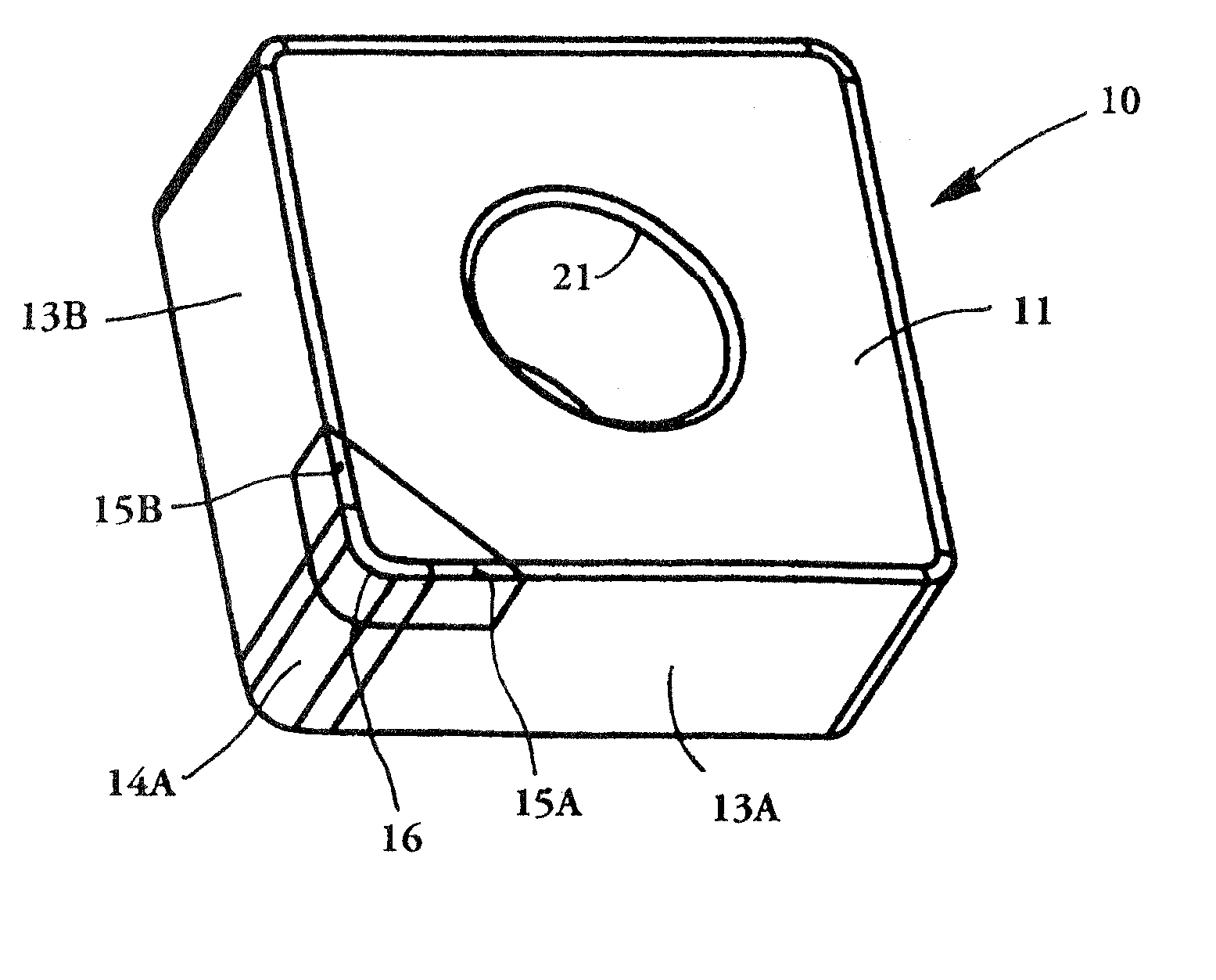
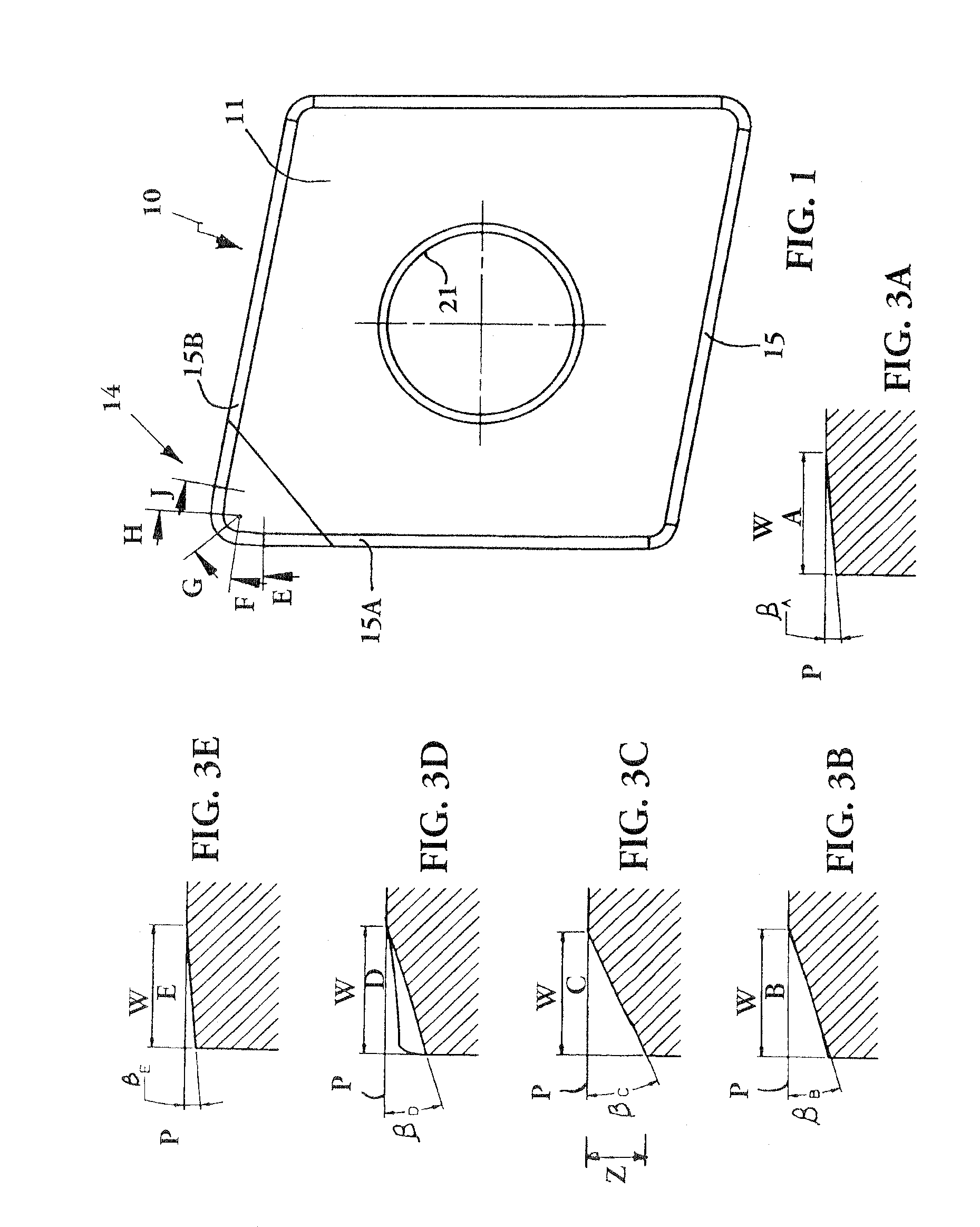
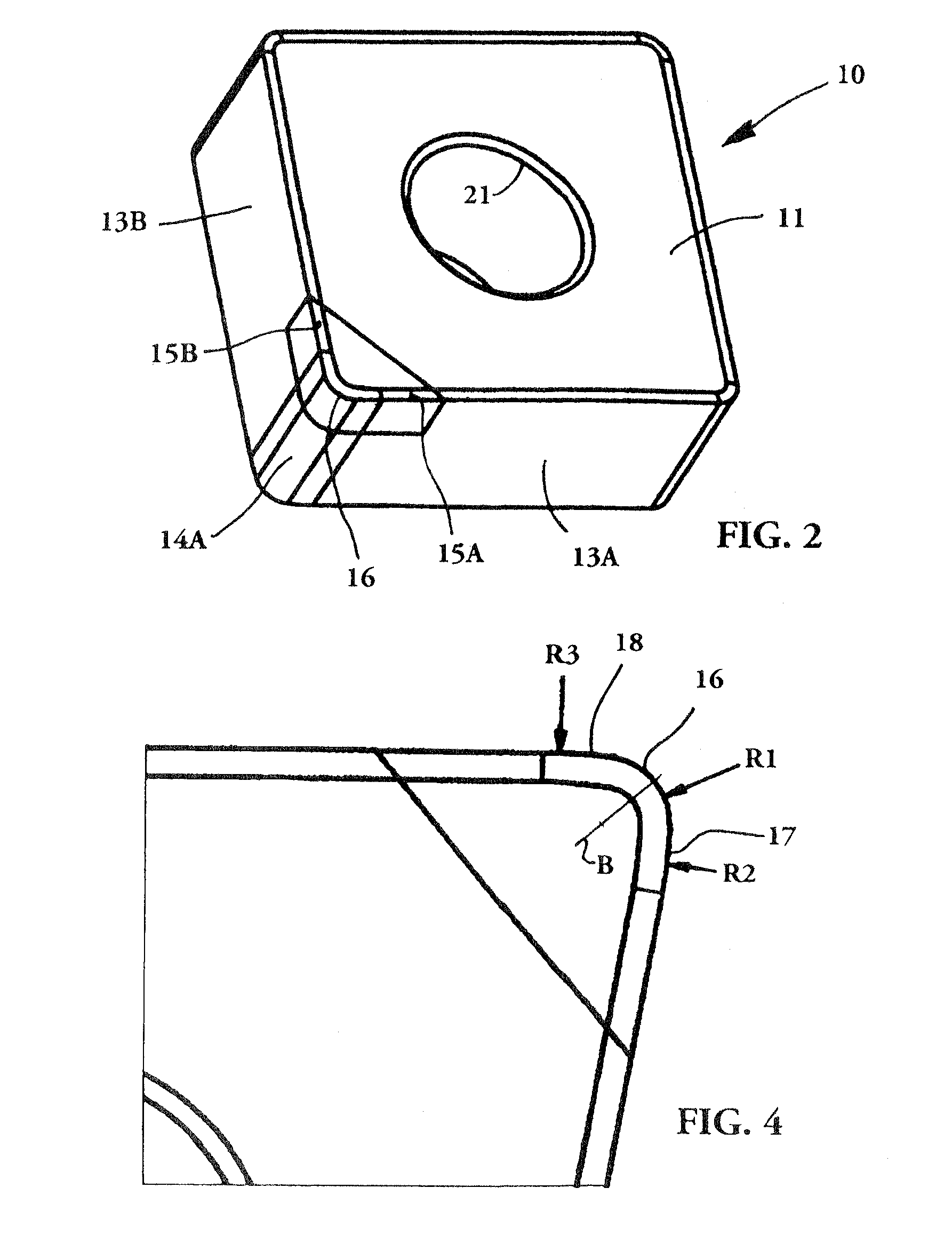
[0026] In FIGS. 1 to 5 a turning cutting insert 10 according to the present invention is shown. The cutting insert may be either single- or double-sided. The cutting insert is rhombic, the corner portion shown in FIG. 1 having a nose angle of about 60 to 80°. However, it may also be square, rectangular, triangular or hexagonal. When it is hexagonal, it may also be in the form of a so-called trigonal insert. The insert in this embodiment is made of cemented carbide having a cubic boron nitride (CBN) corner portion, but may also be made completely of any of those materials or of any other suitable material. The cutting insert 10 comprises an upper surface 11, a lower surface 12 substantially parallel with said upper surface, and at least three side surfaces 13A,13B extending between said upper and lower surfaces. The upper surface 11 is planar in this embodiment and extends perpendicularly relative to said at least three side surfaces. A transition between two adjacent side surfaces 1...


PUM

PropertyMeasurementUnit
nose angleaaaaaaaaaa
angle βAaaaaaaaaaa
angle βBaaaaaaaaaa

Abstract

The present invention relates to a metal cutting insert that is primarily intended for turning operations. The cutting insert comprises an upper surface, a lower surface substantially parallel with said upper surface, and at least three side surfaces extending between said upper and lower surfaces. A transition between two adjacent side surfaces forms a rounded nose radius surface at a cutting insert corner. The cutting insert includes a peripheral land bridging the upper and side surfaces at least at the corner portion at a chamfer angle. An intersection of the land and the nose radius surface forms a nose cutting edge. The nose cutting edge is defined by at least one radius. The cutting corner includes at least one curved wiper edge. The chamfer angle in a cross-section at the nose cutting edge is larger than the chamfer angle in a cross-section a distance away from the nose cutting edge.

Description

BACKGROUND AND SUMMARY [0001] The present invention relates to a metal cutting insert that is primarily intended for turning operations. [0002] For all sorts of turning operations, there is a certain interplay between the feed rate and the corner radius, the corner radius being the connection between the main cutting edge and the secondary cutting edge. The surface fineness produced on the workpiece is specifically influenced by the interplay between the corner radius and the feed rate. The approach angle is defined as the angle between the main cutting edge and the direction of feed. This angle has a considerable influence on the interrelation between the different cutting force components, and thereby also on the surface fineness and dimension accuracy. Surface fineness and dimension accuracy are very sensitive to changes of the approach angle. One problem for all turning operations is to obtain the desired surface fineness. Another problem is poor tool life. [0003] Embodiments of...

Claims


Application Information

Patent Timeline
Patent Type & Authority Applications(United States)
IPC IPC(8): B23B27/16
CPCB23B27/145B23B2200/201B23B2200/245B23B2200/28B23B2200/283B23B2200/3672Y10T407/24B23C2200/208Y10T407/27Y10T407/23Y10T407/235Y10T407/245B23B2226/125B23B27/14B23B27/00
Inventor ALM, PERWICKMAN, ANDERS
Owner SECO TOOLS AB
Why Eureka
Try Eureka