Disposal area for storing substances composite substances or mixtures thereof, method for treating the same, and corresponding device

Inactive Publication Date: 2006-10-12
MUTHER CHRISTOPH
View PDF1 Cites 2 Cited by
  • Summary
  • Abstract
  • Description
  • Claims
  • Application Information

AI Technical Summary

Benefits of technology

[0010] According to another feature of the invention, side walls project from the trough bottom inclined at an angle of 90° to 150°, preferably about 130°. Moreover, the trough bottom is to be inclined at an angle of less than 10° with respect to the horizontal, in order to assist the dissipation of water.
[0041] On account of the simplicity of the core process, the separator and the high throughput that can be seen, the resulting separating costs should actually turn out to the relatively low. The corresponding costs ultimately represent the total use of resources such as transport efficiency, energy, operating efficiency (still associated with the use of resources!), consumption of water, air and land, substitution effect or the like and accordingly the overall effect on the environment. If the amount of successfully treated waste flows and conversion thereof into material flows increases on account of the economic attractiveness of the process, this of course results in a corresponding reduction in the consumption of primary resources on account of the resulting substitution.

Problems solved by technology

These mixtures and composites pose problems in particular in terms of disposal since for a long time separation of the mixtures and of the substances in the composite has not taken place or has taken place only to an unsatisfactory extent at a high cost in terms of energy.
More complex waste cannot be treated for the purpose of material use on account of the lack of technical possibilities or on account of the high costs due for example to wet-chemical processes or thermal processes.

Method used


Image

  • Disposal area for storing substances composite substances or mixtures thereof, method for treating the same, and corresponding device
  • Disposal area for storing substances composite substances or mixtures thereof, method for treating the same, and corresponding device
  • Disposal area for storing substances composite substances or mixtures thereof, method for treating the same, and corresponding device

Examples


Embodiment Construction

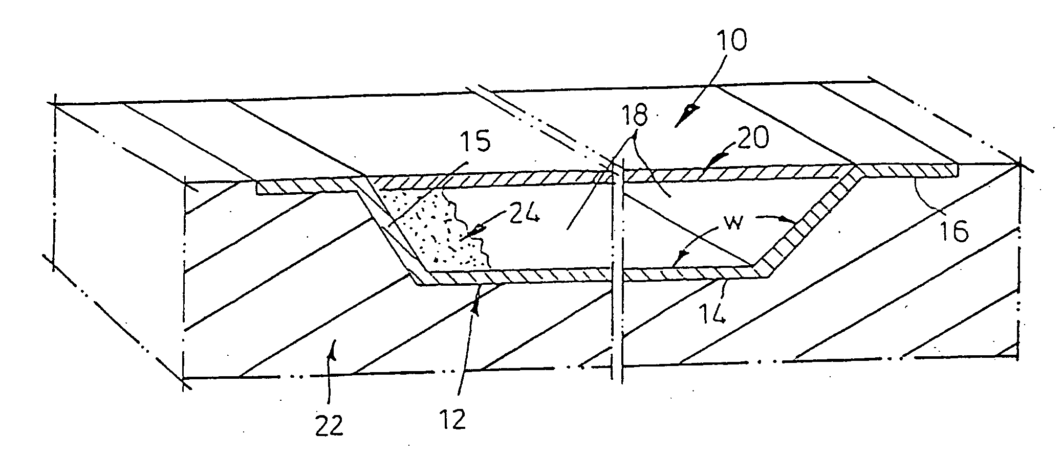
[0056] As shown in FIG. 1, a waste disposal site 10 has a seal against earth 22 carrying groundwater, said seal being designed as a trough 12—with side walls 15 inclined outwards at an angle w of about 130° from the trough bottom 14. The interior 18 of this trough 14 is filled with waste material 24—which is covered over by a covering 20 that lies flush with a trough edge 16.

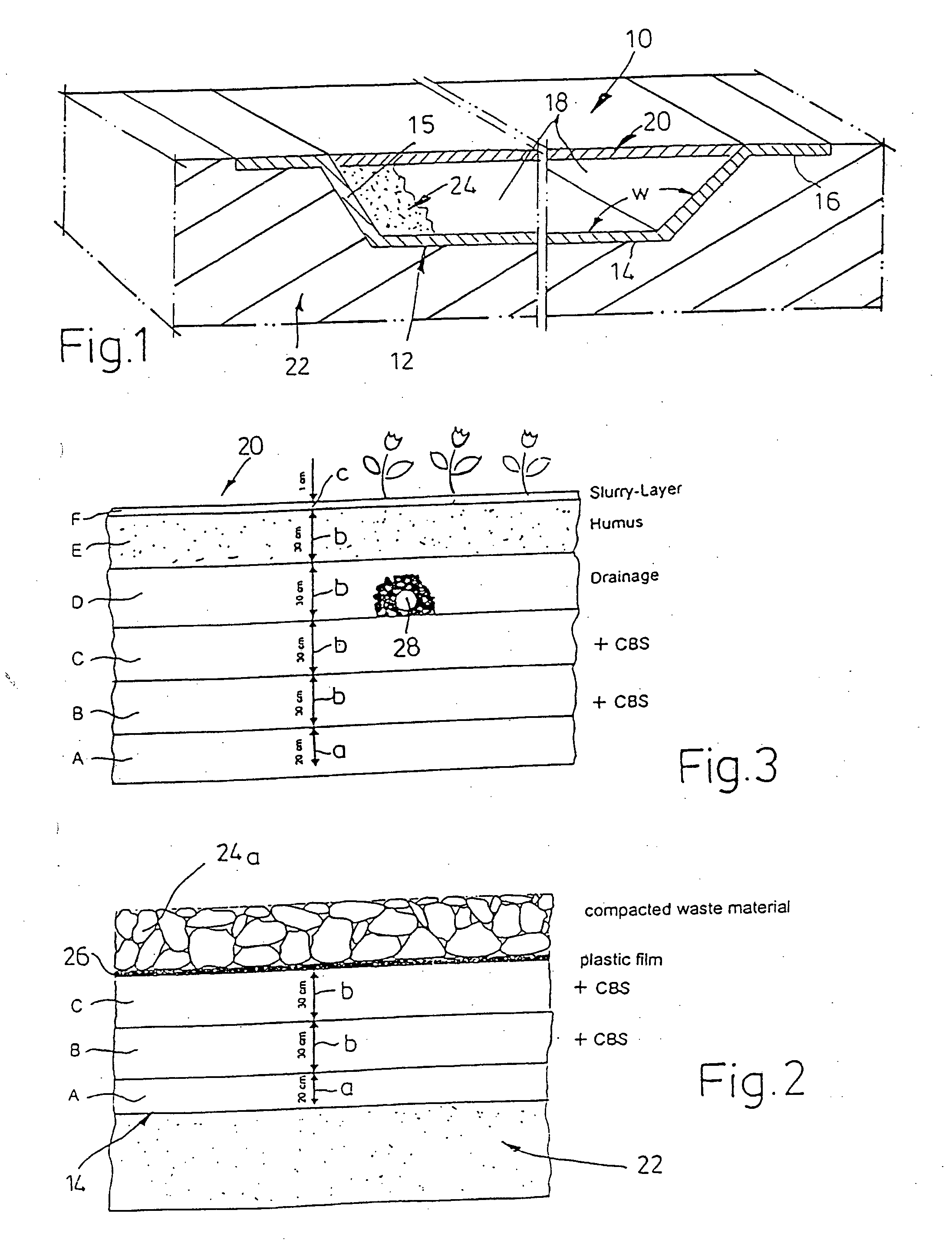
[0057] As shown in FIG. 2, the seal against liquids which could possibly emerge from the waste material 24 towards the bottom is provided by a water-impermeable plastic film 26 which runs below a layer of compacted waste material 24a. The substructure of the trough 12 is produced from water-tight layers A, B and C—said water-tightness resulting from the addition of additives—the thicknesses a (layer A) and b of which measure 200 and 300 mm respectively. Additionally introduced into layers B and C is also what is known as a CBS, a ceramic binder system. The seal against the water-carrying layer of earth 22 is en...


PUM

PropertyMeasurementUnit
Fractionaaaaaaaaaa
Fractionaaaaaaaaaa
Angleaaaaaaaaaa

Abstract

In a waste disposal site for storing waste and residues of solid organic or inorganic substances, composites and mixtures thereof, arranged in the ground (22) is a trough comprising a trough bottom (14) and side walls, the trough bottom of which contains at least two water-tight layers (B, C) with constituents of a ceramic binder system (CBS). Arranged flat between the top water-tight layer (C) and the waste material (24a) is at least one water-tight plastic film (26) on which compacted debris is stored as waste material (24a). Moreover, there is a covering which contains at least two water-tight layers (B, C) on which there is arranged at least one seepage layer for dissipating rainwater.

Description

BACKGROUND OF THE INVENTION [0001] The invention relates to a waste disposal site for storing waste and residues of solid organic and inorganic substances or mixtures thereof and to an apparatus for this purpose. [0002] The abovementioned waste includes for example industrial residues such as slag from the metallurgical industry, but also domestic waste of varying composition. The latter mainly comprises organic mixtures such as foodstuffs, plastic packaging, composite packaging, but also inorganic constituents such as glass, metals and composites thereof. [0003] These mixtures and composites pose problems in particular in terms of disposal since for a long time separation of the mixtures and of the substances in the composite has not taken place or has taken place only to an unsatisfactory extent at a high cost in terms of energy. Most of this waste is incinerated or dumped. Only waste with a small amount of impurities—for example cans made of aluminium sheet—are subject to materia...

Claims


Application Information

Patent Timeline
IPC IPC(8): B09B1/00B03B9/06E02D31/00
CPCB03B9/06E02D31/004B09B1/00Y02W30/62
Inventor MUTHER, CHRISTOPH
Owner MUTHER CHRISTOPH
Why Eureka
Try Eureka