Methods for fabricating fuse elements

a technology of fuse elements and wires, applied in the field of fuse elements, can solve the problems that the known methods for fabricating wire fuse elements, however, are not able to provide varying degrees of resistivity in a cost effective manner, and achieve the effect of reducing the first electrical resistivity of the wire, and high resistan

Inactive Publication Date: 2006-10-19
COOPER TECH CO
View PDF4 Cites 3 Cited by
  • Summary
  • Abstract
  • Description
  • Claims
  • Application Information

AI Technical Summary

Benefits of technology

[0006] In another aspect, a method for fabricating wire fuse elements is provided. The method includes providing a continuously extending high resistance fuse wire having a first electrical resistivity, the wire being overlaid with a conductive material, thereby reducing the first electrical resistivity of the wire to a second electrical resistivity lower than the first electrical resistivity. The me

Problems solved by technology

Known methods for fabricating wire fuse elements, however, are not capable of prov

Method used


Image

  • Methods for fabricating fuse elements
  • Methods for fabricating fuse elements
  • Methods for fabricating fuse elements

Examples


Embodiment Construction

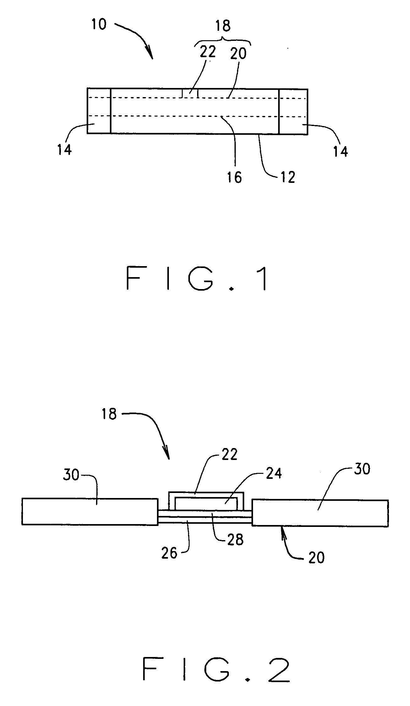
[0015]FIG. 1 is a schematic illustration of an exemplary indicating fuse 10 applicable to the present invention. The fuse 10 is a cylindrical cartridge fuse, and includes an insulative (i.e., nonconductive) fuse body 12, two conductive end caps or terminal elements 14 attached to the fuse body 12 on either end thereof, a primary fuse link 16 extending between and electrically connected to the terminal elements 14, and a fuse state indicator 18. In an exemplary embodiment, the fuse 10 is connected to line side and load side electrical circuitry (not shown) through the terminal elements 14, thereby forming a current path through the primary fuse link 16.

[0016] In an exemplary embodiment, the fuse body 12 is elongated and is generally cylindrical, and the terminal elements 14 are generally cap shaped and complementary in shape to the fuse body 12. It is appreciated, however, that other shapes and configurations of the fuse body 12 and the terminal elements 14 may be provided in altern...


PUM

PropertyMeasurementUnit
Electrical resistanceaaaaaaaaaa
Electrical conductoraaaaaaaaaa
Electrical resistivityaaaaaaaaaa

Abstract

A method for fabricating wire fuse elements is provided. The method includes providing a continuously extending high resistance fuse wire having a first electrical resistivity. The method also includes applying a conductive material to the wire, and reducing the first electrical resistivity of the wire to a second electrical resistivity lower than the first electrical resistivity. The method also includes selectively removing a portion of the conductive material from the wire, and forming at least one high resistance portion having the first electrical resistivity wherein the conductive material is removed, and the wire having the second electrical resistivity in portions thereof wherein the conductive material remains.

Description

BACKGROUND OF THE INVENTION [0001] This invention relates generally to fuse elements, and, more particularly, to methods for fabricating wire fuse elements. [0002] Fuses are widely used as overcurrent protection devices to prevent costly damage to electrical circuits. Fuse terminals typically form an electrical connection between an electrical power source and an electrical component or a combination of components arranged in an electrical circuit. A fusible link is connected between the fuse terminals, so that when electrical current flowing through the fuse exceeds a predetermined limit, the fusible link melts and opens the circuit through the fuse to prevent electrical component damage. [0003] Fuse indicators have been developed for various types of fuses to facilitate identification of inoperable fuses due to an opened fuse link. Fuses including such indicators, sometimes referred to as indicating fuses, typically include a high resistivity secondary fuse link and in indicator e...

Claims


Application Information

Patent Timeline
IPC IPC(8): H01H69/02H05K3/02H01F7/06
CPCH01C3/06H01H69/02Y10T29/49071Y10T29/49107Y10T29/49156
Inventor DOWIL, MATTHEW THOMAS
Owner COOPER TECH CO
Why Eureka
Try Eureka