Eureka AIR delivers breakthrough ideas for toughest innovation challenges, trusted by R&D personnel around the world.

Nondestructive testing apparatus

Inactive Publication Date: 2006-10-19
MI SUNG C&S INSPECTION
View PDF5 Cites 9 Cited by
  • Summary
  • Abstract
  • Description
  • Claims
  • Application Information

AI Technical Summary

Benefits of technology

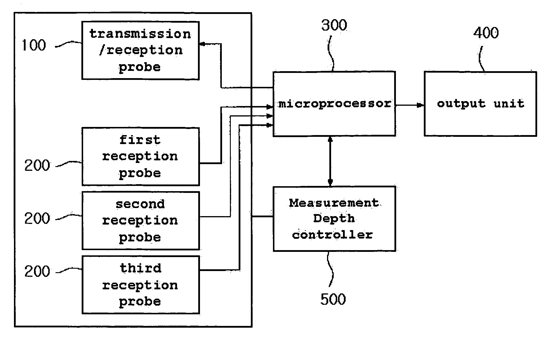
[0018] Therefore, the present invention has been made in view of the above problems, and it is an object of the invention to provide a nondestructive testing apparatus for inspecting an internal part of a large-diameter pile using a single transmission/reception probe capable of transmitting/receiving ultrasound of more than 50 kHz and a plurality of reception probes, digitizing a received frequency, and outputting the inspection result.
[0019] In accordance with the present invention, the above and other objects can be accomplished by the provision of a nondestructive testing apparatus, comprising: a transmission/reception probe which is inserted into a hole formed in a partition of a concrete structure, generates ultrasound of more than 50 KHz in a radial direction of 360°, and receives the reflected ultrasound after the ultrasound

Problems solved by technology

The above-mentioned bridge or harbor structure may collapse if unexpected holes occur during a curing period for a concrete pile contained in the structure, such that the necessity of estimating if the structure is in a normal state has been rapidly increased.
However, the first method, in which the user performs excavation and views the damage of the concrete pile, requests a large-sized excavating operation, such that it requires large-scale equipment, and consumes an unnecessary long period of time and great cost.
The second method using the elastic waves has poor precision, such that it must be used along with the above-mentioned first method at the same time.
The third method using the clinometer requires boring, such that it consumes an unnecessary long period of time and great cost.
Also, the nondestructive testing apparatus entirely depends on a manual operation of a user who carries out the nondestructive testing, such that reliability of the quality testing result is deteriorated if the user is unskilled at the quality testing or makes an unexpected mistake.
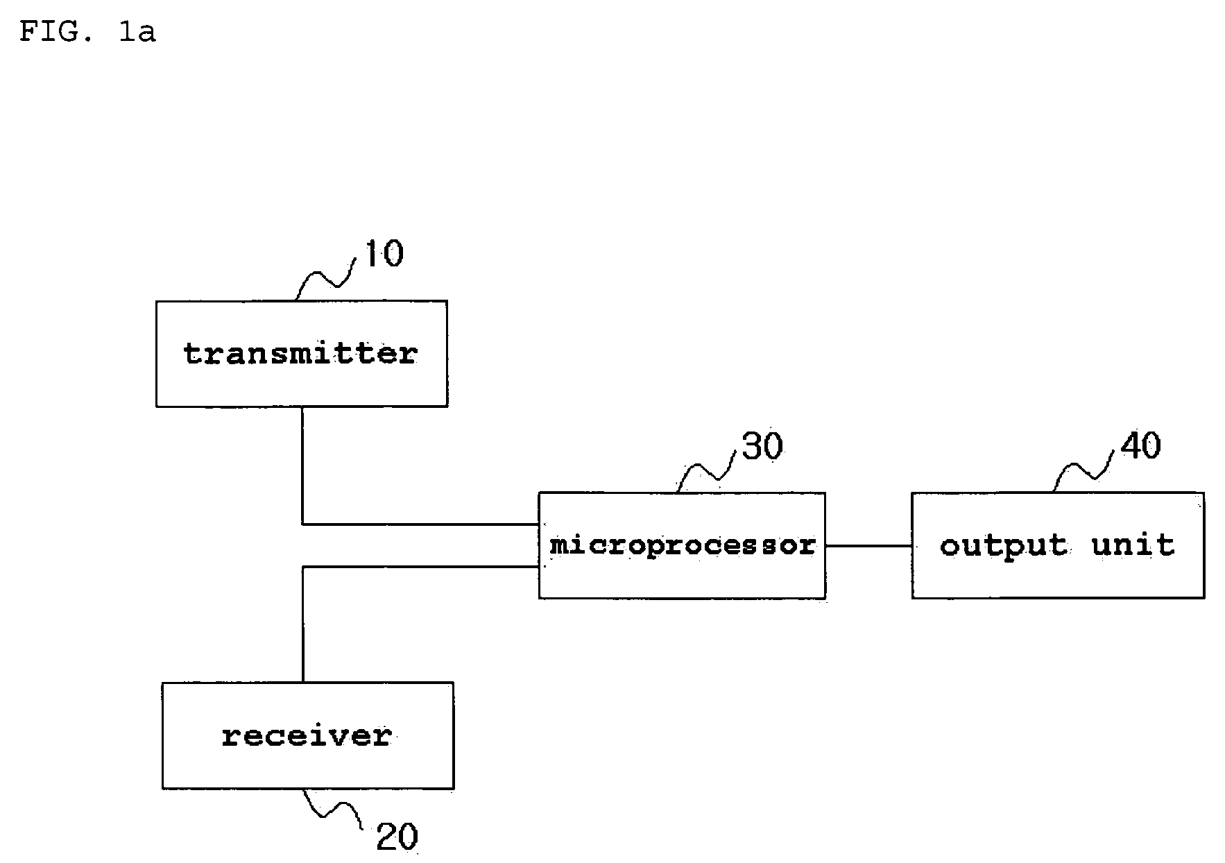
Also, the user must hold the transmitter 10 and the receiver 20, or must attach the same to a necessary part, such that it has difficulty in performing the above-mentioned testing on inaccessible areas such as the seabed and the subterranean parts.
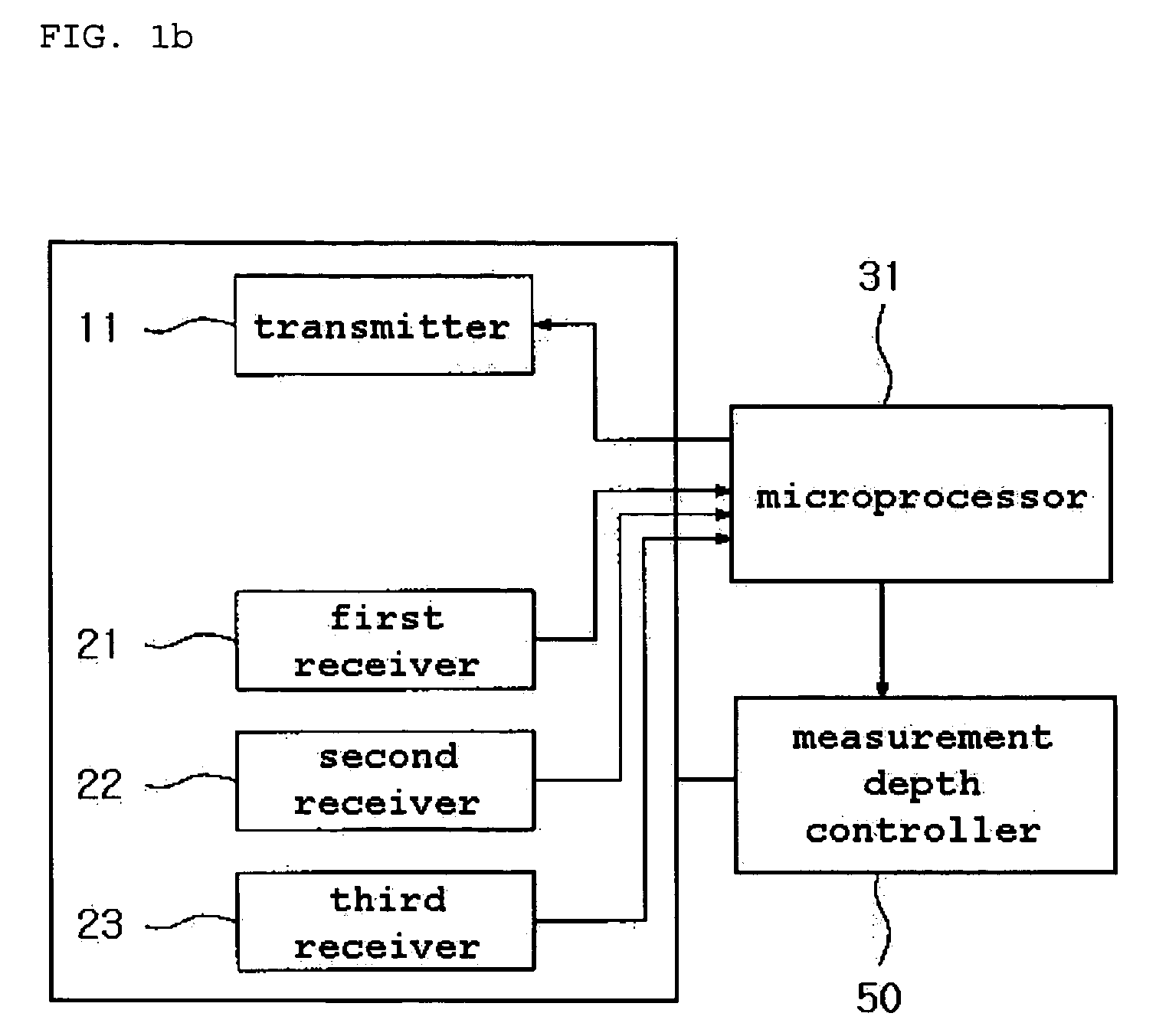
In this case, although the nondestructive testing apparatus shown in FIG. 1b is able to perform an overall quality test of the structure using only one transmission / reception process, it uses a low frequency of about 50 kHz as a transmission frequency, such that it is unable to recognize a defect of the structure.
According to the first problem, the conventional nondestructive testing apparatus cannot detect small-sized defects of less than a predetermined size.
It is impossible for the transmission / reception probe for use in the conventional concrete nondestructive testing apparatus to detect an internal defect (e.g., a cold joint) of the concrete of less than 5 cm.
According to the second problem, the conventional nondestructive testing apparatus cannot recognize a defect in three dimensions.
However, the above method requires analysis of th upper / lower homogeneity of the concrete using the logging of the transmission / reception probes, and requires analysis of data of a reception point at different vertical distance transmission locations using the same logging, such that it has difficulty in measuring position and size information of a concrete defect oriented vertically in a large-diameter pile.
In order to measure the position and size of the defect contained in the concrete, a plurality of measurement holes must be buried before constructing the large-diameter pile, resulting in consumption of an unnecessarily long period of time and great cost.
The conventional nondestructive testing apparatus analyzes the data obtained by the above-mentioned process, and predicts only the size of the defect contained in the concrete, such that it is unable to measure at least two-dimensional result.
According to the third problem, the conventional nondestructive testing apparatus is configured in the form of an analog signal reception system as shown in FIG. 1d, such that its inspection function is limited.
In other words, a transmission probe for use in the conventional nondestructive testing apparatus generates a resonance frequency of 50 kHz, and uses a long wavelength due to the resonance frequency of 50 kHz, such that the conventional nondestructive testing apparatus is unable to predict a small defect contained in the concrete whereas it has a very long ultrasound measurement distance.
Also, the conventional nondestructive testing apparatus has a limitation in performing a gain control operation.
As a result, the initial ultrasound arrival time denoted by the waveform shown in FIG. 1d is generated in almost the last part of the waveform, such that the conventional nondestructive testing apparatus has difficulty in analyzing reception data.
As a result, the above-mentioned nondestructive testing apparatus is unable to measure a horizontal length of the defect and energy variation.
In addition, if the width of the concrete structure is increased, the size of the time division is higher than 1000 μs, such that the nondestructive testing apparatus is unable to detect concrete defects.

Method used


Image

  • Nondestructive testing apparatus
  • Nondestructive testing apparatus
  • Nondestructive testing apparatus

Examples


Embodiment Construction

[0031] Now, preferred embodiments of the present invention will be described in detail with reference to the annexed drawings. In the drawings, the same or similar elements are denoted by the same reference numerals even though they are depicted in different drawings. In the following description, a detailed description of known functions and configurations incorporated herein will be omitted when it may make the subject matter of the present invention rather unclear.

[0032]FIG. 2 is a block diagram illustrating a nondestructive testing apparatus according to the present invention. FIG. 3a is a block diagram illustrating a microprocessor according to the present invention. FIG. 3b shows the appearance of an exemplary microprocessor according to the present invention. FIG. 4 shows internal configurations of a transmission / reception probe and a reception probe according to the present invention.

[0033] In order to use the nondestructive testing apparatus shown in FIG. 2 according to t...


PUM


Abstract

A nondestructive testing apparatus inspects an internal part of a large-diameter pile using both a single transmission / reception probe for transmitting / receiving an ultrasound signal of more than 50 kHz and a plurality of reception probes, digitally processes the received frequency, and outputs the inspected result.

Description

BACKGROUND OF THE INVENTION [0001] 1. Field of the Invention [0002] The present invention relates to a nondestructive testing apparatus, and more particularly to a nondestructive testing apparatus capable of testing quality of a large-sized structural concrete partition buried in the seabed or in the earth, for example, a large-diameter placing pile, and Caisson line, etc. [0003] 2. Description of the Related Art [0004] With increasing industrialization, fundamental components indicative of large-sized structures, such as bridges and harbors, have been rapidly increased. The above-mentioned bridge or harbor structure may collapse if unexpected holes occur during a curing period for a concrete pile contained in the structure, such that the necessity of estimating if the structure is in a normal state has been rapidly increased. [0005] There have been widely used first to third methods to estimate if the structure is in a normal state. In the case of the first method, a user excavates...

Claims


Application Information

Patent Timeline
IPC IPC(8): G01N29/00
CPCG01N29/07G01N29/348G01N33/383G01N2291/0232G01N2291/103G01N2291/02854G01N2291/044G01N2291/101G01N2291/0258B60G7/04F16F1/38B60G2204/41B60G2204/41062B60G2206/012
Inventor KIM, SUNG
Owner MI SUNG C&S INSPECTION
Why Eureka
Eureka Blog
Learn More