Wireless oil filter sensor

a sensor and oil filter technology, applied in the field of sensing devices, can solve the problems of increased mass loading of the saw sensor, small frequency changes caused by small changes in viscosity of highly viscous liquids, and very small frequency changes of the viscosity, etc., and achieve the effect of improving the accuracy of the sensor

Inactive Publication Date: 2006-10-19
HONEYWELL INT INC
View PDF16 Cites 39 Cited by
  • Summary
  • Abstract
  • Description
  • Claims
  • Application Information

AI Technical Summary

Benefits of technology

[0012] The aforementioned aspects and other objectives and advantages can now be achieved as described herein. A wireless oil filter sensing system is described. Such a system includes an engine oil filter and a sensing mechanism that is connectable to the oil filter. The sensing mechanism includes one or more acoustic wave sensing elements and an antenna that communicates with the acoustic wave sensing element(s). The acoustic wave sensing element(s) could be excited by an external interrogator which includes a receiver and a transmitter. When the acoustic wave sensing elements are in contact with oil contained in the oil filter, the acoustic wave sensing elements detect acoustic waves associated with the oil in response to an excitation of the wave sensing elements, thereby generating data indicative of the quality of the oil for wireless transmission through the antenna.

Problems solved by technology

Most acoustic wave chemical detection sensors, for example, rely on the mass sensitivity of the sensor in conjunction with a chemically selective coating that absorbs the vapors of interest resulting in an increased mass loading of the SAW sensor.
The frequency changes caused by small changed in viscosity of highly viscous liquids, however, are very small.
Because of the highly viscous loading, the signal from a sensor oscillator is very “noisy” and the accuracy of such measurement systems is very poor.

Method used


Image

  • Wireless oil filter sensor
  • Wireless oil filter sensor
  • Wireless oil filter sensor

Examples


Embodiment Construction

[0026] The particular values and configurations discussed in these non-limiting examples can be varied and are cited merely to illustrate at least one embodiment and are not intended to limit the scope thereof.

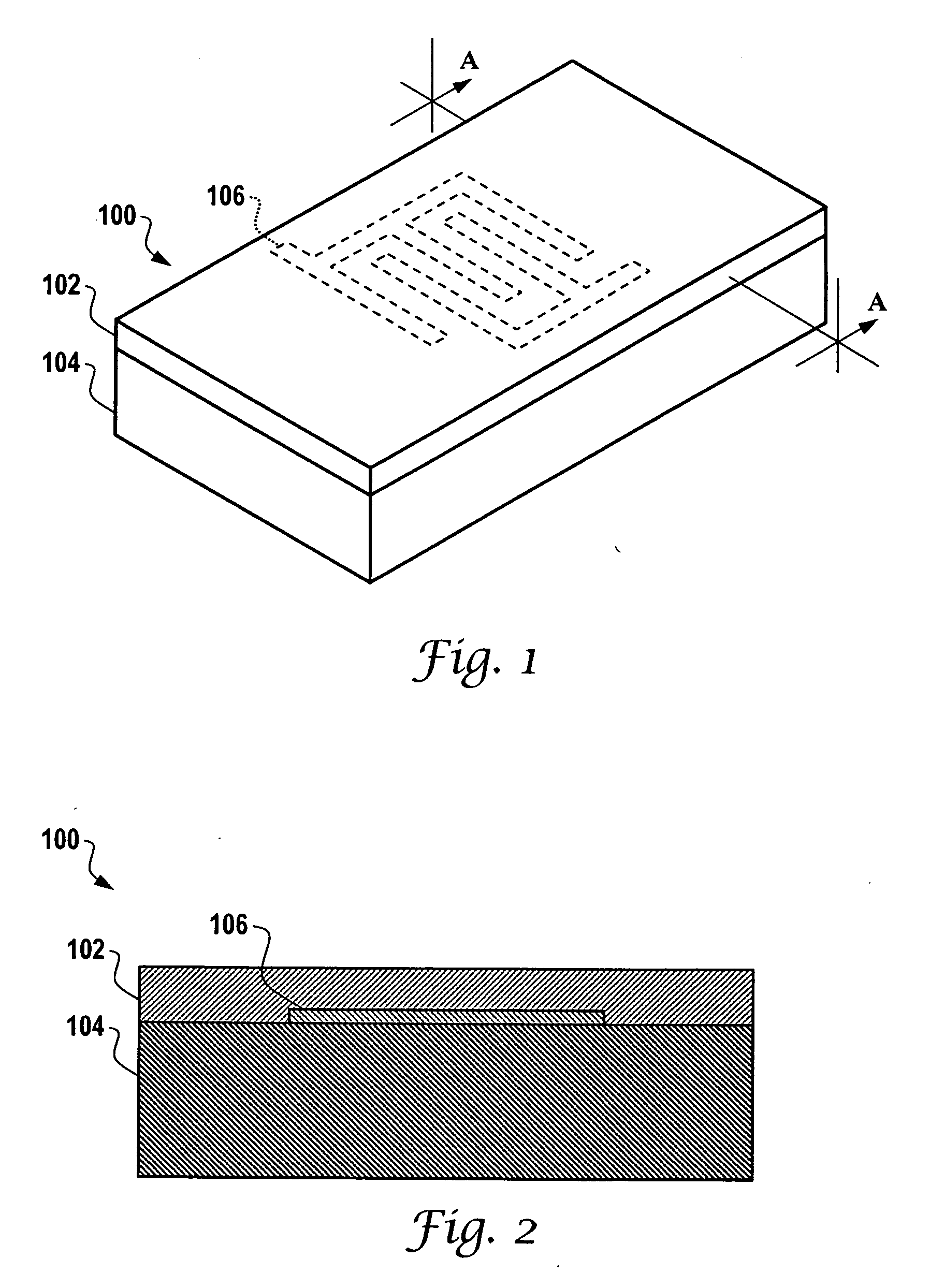
[0027]FIG. 1 illustrates a perspective view of an interdigital surface wave device 100, which can be implemented in accordance with one embodiment. Shear horizontal surface wave device (SH-SAW) 100 generally includes an interdigital transducer 106 formed on a piezoelectric substrate 104. The surface wave device 100 can be implemented in the context of a sensor chip. Interdigital transducer 106 can be configured in the form of an electrode, depending upon design considerations.

[0028] Note that the interdigital surface wave device 100 represents only one type of acoustic wave device that can be adapted for use with the embodiments disclosed herein. It can be appreciated that a variety of other types (e.g., SH-SAW, BAW, APM, SH-APM, FPW, SH-SAW-DL, SH-SAW-R, etc.) can be utiliz...


PUM

PropertyMeasurementUnit
thicknessaaaaaaaaaa
thicknessaaaaaaaaaa
velocityaaaaaaaaaa

Abstract

A wireless oil filter sensing system includes an oil filter and a sensing mechanism that is connectable to the oil filter. The sensing mechanism includes one or more acoustic wave sensing elements and at least one antenna that communicate with the acoustic wave sensing element(s). An external interrogation system could excite the acoustic wave sensing element(s) wireless and passively. When the acoustic wave sensing elements are in contact with oil contained in the oil filter, the acoustic wave sensing elements detect acoustic waves associated with the oil in response to an excitation of the acoustic wave sensing elements, thereby generating data indicative of the quality of the oil for wireless transmission through the antenna(s).

Description

TECHNICAL FIELD [0001] Embodiments are generally related to sensing devices and components thereof. Embodiments also relate to oil quality detection inside an oil filter. Embodiments additionally relate to different types of acoustic waves devices, such as shear horizontal surface acoustic wave (SH-SAW), flexural plate wave (FPW), Love mode, acoustic plate mode (APM), shear horizontal acoustic plate mode (SH-APM), and bulk acoustic waves (BAW), including thickness shear mode, torsional mode, and flexural mode components and devices thereof. Embodiments additionally relate to the wireless transmission of detection data. BACKGROUND OF THE INVENTION [0002] Acoustic wave sensors are utilized in a variety of sensing applications, such as, for example, temperature and / or pressure sensing devices and systems. Acoustic wave devices have been in commercial use for over sixty years. Although the telecommunications industry is the largest user of acoustic wave devices, they are also used for c...

Claims


Application Information

Patent Timeline
Patent Type & Authority Applications(United States)
IPC IPC(8): G01N29/00
CPCB01D35/143G01N29/022G01N29/4481G01N33/26G01N33/28G01N2291/0427G01N2291/0256G01N2291/0421G01N2291/0422G01N2291/0426G01N2291/0226B01D27/00G01S13/75G01N29/44
Inventor LIU, JAMES ZTRHODES, MICHAEL L.RAHMAN, AZIZ
Owner HONEYWELL INT INC
Why Eureka
Try Eureka