Plasma display panel

Inactive Publication Date: 2006-10-19
PANASONIC CORP
View PDF4 Cites 19 Cited by
  • Summary
  • Abstract
  • Description
  • Claims
  • Application Information

AI Technical Summary

Benefits of technology

[0007] According to such a configuration, impurity gas inside the PDP is decomposed by an oxidation catalyst provided in the reflective layer so as to reduce the impurity gas influencing the det

Problems solved by technology

Main components of the impurity gas include water, carbon dioxide, hydrocarbon gas, and the like, and these impurity gases are adsorbed on a phosphor etc. in the PDP and may cause such problems as deterioration of discharge characteristics, degradation of luminance, and the like (disclosed in Japanese Patent Unexamined Publication No. 2003-281994 and FPD Technology Outlook (Electronic Journal, Oct. 25, 2000, pp 615-618)).
Therefore, one of the important problems is to reduce impurity gas inside the PDP and to improve the reliability by stabilizing discharge characteristics and suppressing change over time.
Consequently, removal of impurity gas was not sufficient.
Furthermore, in the method of providin

Method used


Image

  • Plasma display panel
  • Plasma display panel
  • Plasma display panel

Examples


first exemplary embodiment

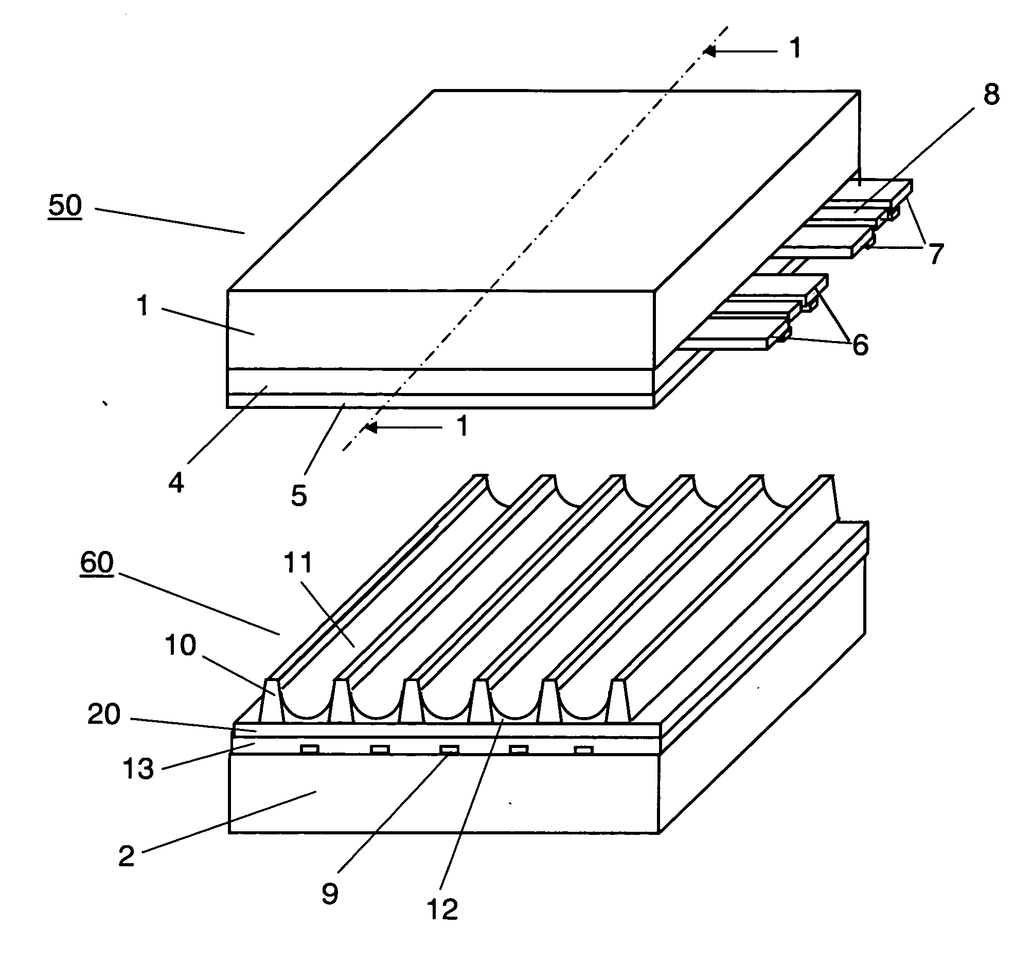
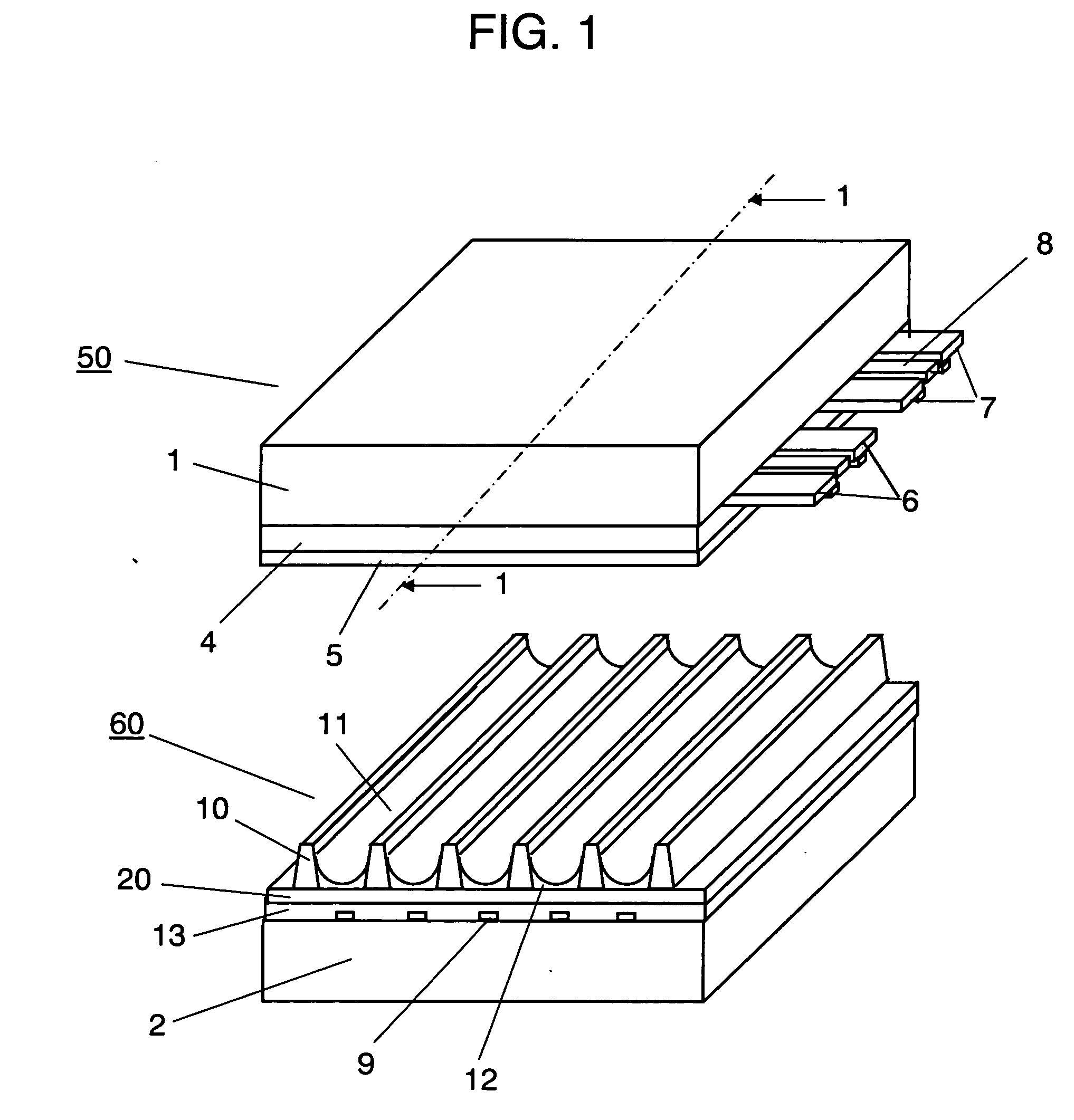
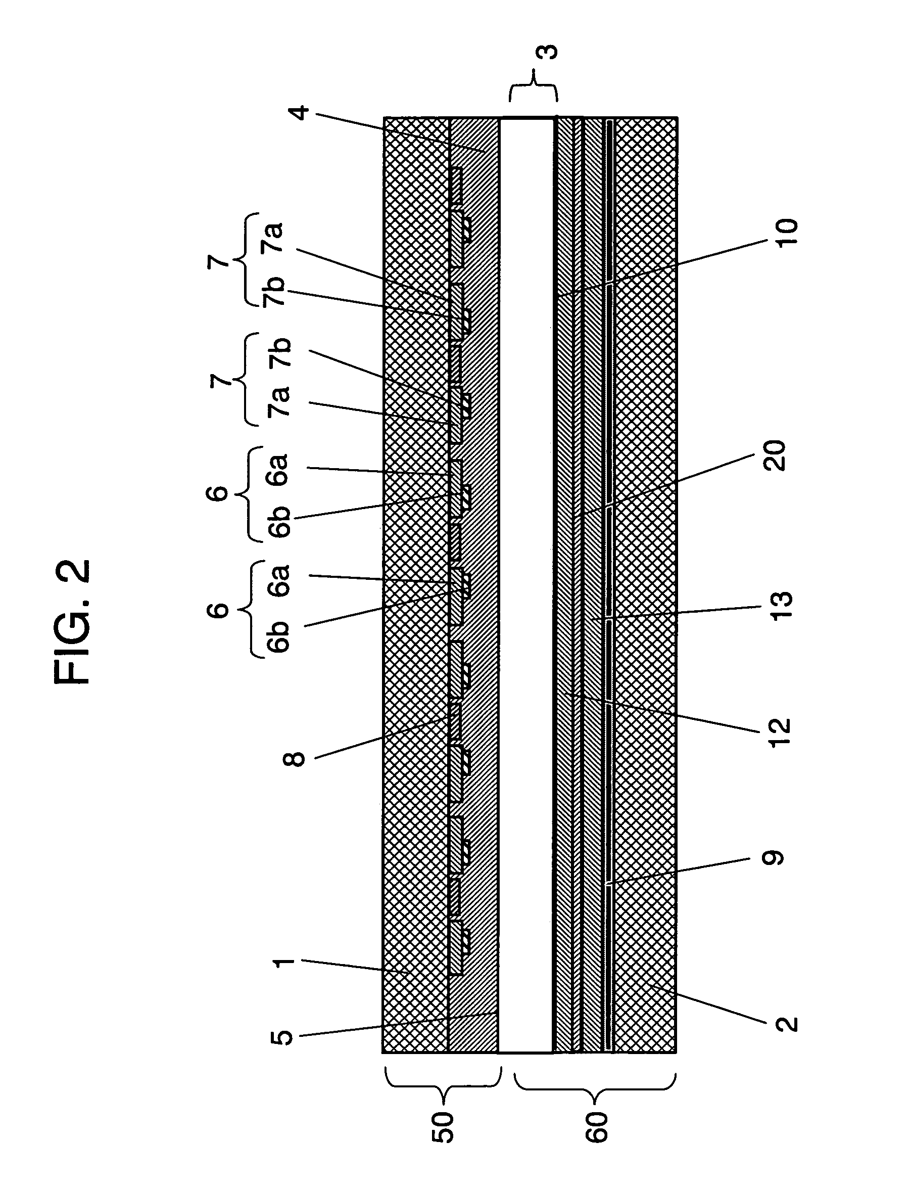
[0036]FIG. 1 is an exploded perspective view showing a PDP in accordance with a first exemplary embodiment of the present invention. FIG. 2 is a sectional view taken along line 1-1 of FIG. 1.

[0037] As shown in FIGS. 1 and 2, a PDP has a configuration in which front panel 50 including front glass substrate 1 etc. and rear panel 60 including rear glass substrate 2, etc. are disposed opposing each other with discharge space 3 interposed therebetween, and front panel 50 and rear panel 60 are air-tightly sealed together with a sealing material (not shown) at the peripheries. In discharge space 3, discharge gas radiating ultraviolet ray by discharge, for example, neon (Ne) and xenon (Xe), is filled in at a pressure of 400 Torr (53.2 KPa) to 600 Torr (79.8 KPa).

[0038] On front substrate 1 of front panel 50, band-like display electrodes composed of a pair of scan electrode 6 and sustain electrode 7 are disposed in parallel to each other. Scan electrode 6 and sustain electrode 7 are respec...

second exemplary embodiment

[0048]FIG. 3 is a sectional view showing a configuration of a rear panel of a PDP in accordance with a second exemplary embodiment of the present invention. Main configurations of a front panel and a rear panel of the PDP in the second exemplary embodiment are the same as those in the first exemplary embodiment and so description thereof omitted herein. As shown in FIG. 3, in the second exemplary embodiment, reflective layer 21 in which an oxidation catalyst is dispersed is formed on the entire surface of the inner wall of discharge cells 11. That it to say, barrier ribs 10 are formed on dielectric layer 13, and reflective layer 21 having the same material composition mentioned in the first exemplary embodiment in which an oxidation catalyst is dispersed is formed on the side surfaces of barrier ribs 10 and on dielectric layer 13 in discharge cells 11. Phosphor layer 12 is formed on reflective layer 21. As a method of forming such a reflective layer 21, similar to the method of form...

third exemplary embodiment

[0055]FIG. 4 is a sectional view showing a configuration of a PDP in accordance with a third exemplary embodiment of the present invention. FIG. 5 is a perspective view showing a rear panel. Main configurations of a front panel and a rear panel of the PDP in the third exemplary embodiment are the same as those in the first exemplary embodiment and detailed configuration of the rear panel is different.

[0056] As shown in FIG. 4, on the rear substrate 2, a plurality of band-like data electrodes 9 are disposed in parallel to each other in the direction perpendicular to scan electrodes 6 and sustain electrodes 7. Dielectric layer 13 covers data electrodes 9. On dielectric layer 13, reflective layer 20 containing an oxidation catalyst is formed. Furthermore, on reflective layer 20, barrier ribs 10 partitioning discharge space 3 to form discharge cells 11 are provided.

[0057] As shown in FIGS. 4 and 5, barrier ribs 10 are composed of longitudinal barrier ribs 10a as first barrier ribs ext...


PUM


Abstract

A plasma display panel having an excellent image display quality and high reliability is provided by preventing deterioration of a phosphor due to hydrocarbon gas remaining in the plasma display panel. The plasma display panel includes front panel (50) and rear panel (60) disposed opposing each other, and front panel (50) is provided with a plurality of display electrodes composed of a pair of scan electrode (6) and sustain electrode (7), and rear panel (60) has barrier ribs (10) forming discharge cells (11). In the plasma display panel, rear panel (60) includes data electrodes (9) perpendicular to display electrodes composed of a pair of scan electrode (6) and sustain electrode (7) on substrate (2), dielectric layer (13) covering data electrodes (9), reflective layer (20) containing an oxidation catalyst and covering at least a part of dielectric layer (13), and phosphor layer (12) covering reflective layer (20).

Description

TECHNICAL FIELD [0001] The present invention relates to a plasma display panel (hereinafter, referred to as “PDP”) used for, for example, a television, a large-screen monitor, and the like, and particularly to a PDP in which impurity gas is reduced. BACKGROUND ART [0002] Recently, in color display devices used for displaying images on computers, televisions, and the like, a PDP display device using a PDP has draw attention as a color display device that can realize a large-screen and light weight display device. [0003] A PDP includes a front panel and a rear panel sealed to each other with predetermined discharge space interposed therebetween. On the front panel and the rear panel, an electrode and a dielectric layer, or a barrier rib, a phosphor layer, and the like, are formed respectively by firing a structure containing an organic binder. Among the production processes of a PDP, in particular, in a sealing process for sealing the front panel and the rear panel, an organic binder,...

Claims


Application Information

Patent Timeline
IPC IPC(8): H01J17/49H01J17/16
CPCH01J11/12H01J2211/442H01J11/44H01J11/32H01J11/36H01J2211/366
Inventor SUGIMOTO, KAZUHIKOAOKI, MASAKIMIYAMAE, YUICHIROHORIKAWA, KEIJIHIBINO, JUNICHITANAKA, YOSHINORISETOGUCHI, HIROSHITOYODA, IZUMI
Owner PANASONIC CORP
Why Eureka
Try Eureka