
Circular-polarization dipole helical antenna

a dipole helical antenna and circular polarization technology, applied in the direction of antennas, antenna feed intermediates, non-resonant long antennas, etc., can solve the problems of lack of fine-tuning ability, narrower bandwidth, complex structure of this antenna, etc., to achieve fast fine-tuning, low loss, and high dielectric constant material

Inactive Publication Date: 2006-10-19
CIREX TECH CORP
View PDF3 Cites 174 Cited by
  • Summary
  • Abstract
  • Description
  • Claims
  • Application Information

AI Technical Summary

Benefits of technology

[0008] The present invention provides a circular-polarization dipole helical antenna with compact and cylindrical dielectric, dipole helical antenna conductors and unbalance-to-balance circuit module, whereby the circular-polarization dipole helical antenna can be fast fine-tuned to electronic device and satellite equipment.
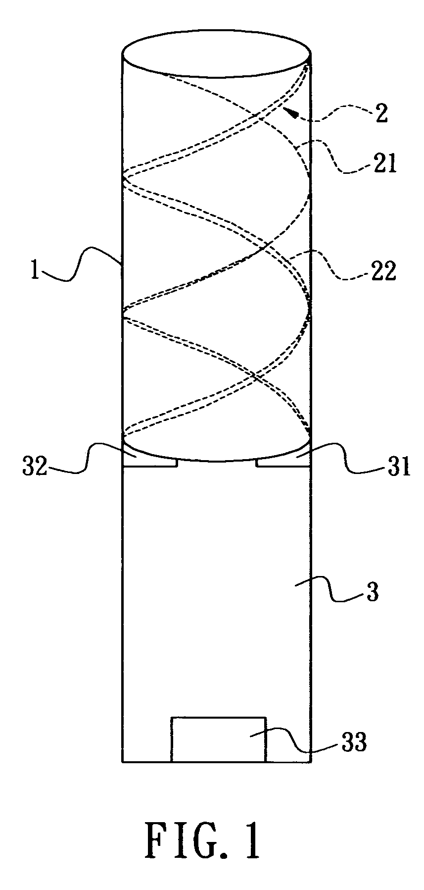
[0009] Accordingly, the present invention provides a circular-polarization dipole helical antenna used for electronic device and satellite terminal and comprising a base, and an antenna conductor arranged on surface of the base. The antenna conductor comprises a plurality of metal conductors with high Q value and anti-oxidation property and continuously and helically coated on surface of the base. The base is made of low loss and high dielectric constant material. An unbalance-to-balance circuit module connects two signal-feeding ends to the base with phase difference of 180 degree. The problems of narrow bandwidth, low efficiency, complicated structure and precise manufacture can be solved.

Problems solved by technology

However, the above-mentioned antenna has helical design, which has narrower bandwidth and is lack of fine-tuning ability.
The structure of this antenna is complicated and the cost of this antenna is high.

Method used


Image

  • Circular-polarization dipole helical antenna
  • Circular-polarization dipole helical antenna
  • Circular-polarization dipole helical antenna

Examples


Embodiment Construction

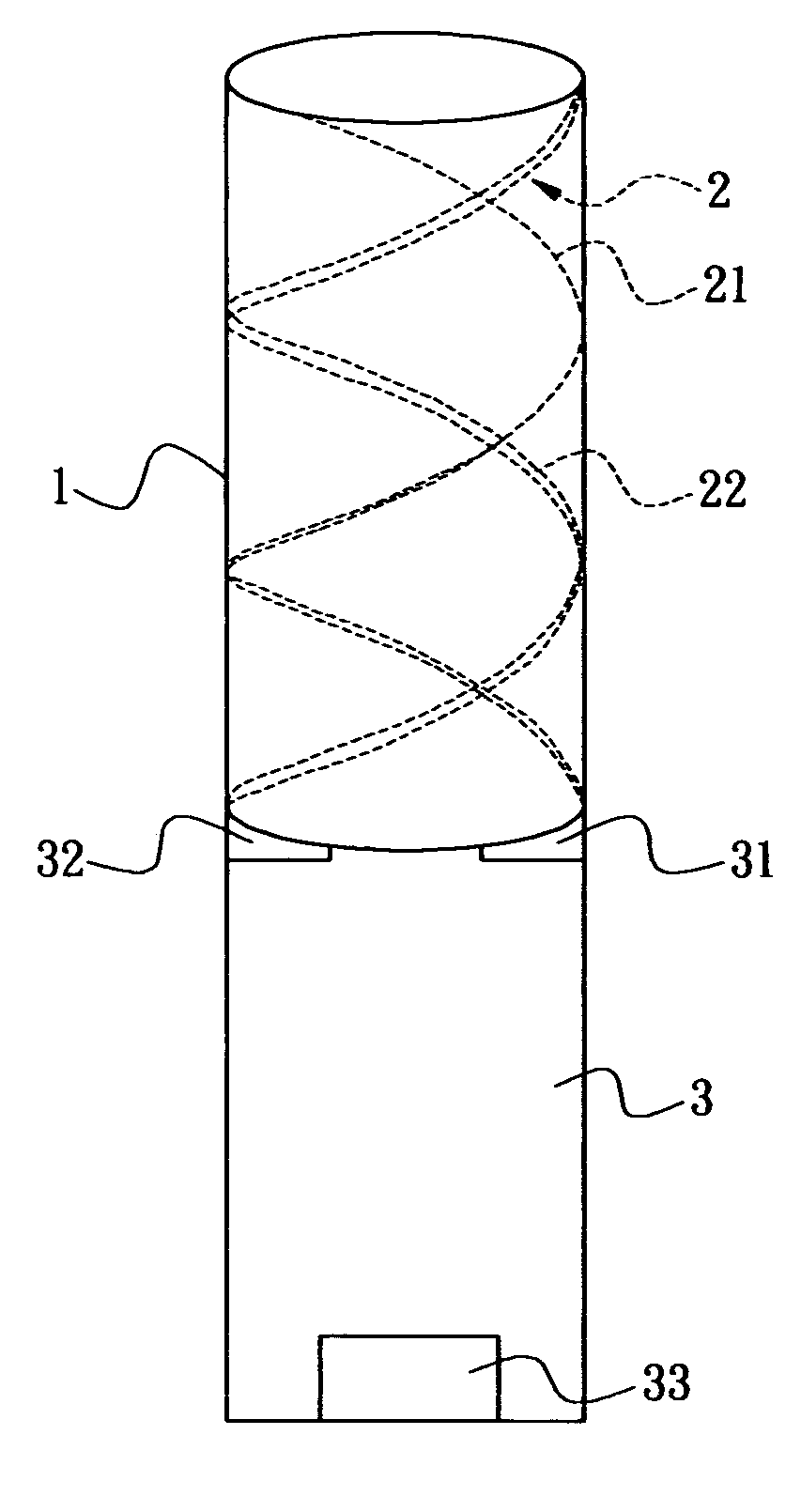
[0014]FIG. 1 shows a sectional view of the circular-polarization dipole helical antenna of the present invention. The circular-polarization dipole helical antenna of the present invention comprises a base 1 and an antenna conductor 2 continuously arranged on the surface of the base 1. An unbalance-to-balance circuit module 3 is used connected the circular-polarization dipole helical antenna to a transmission circuit, thus achieving a compact and fast-tuning circular-polarization antenna. The circular-polarization antenna can be advantageously used in applications such as mobile phone, GPS, SDAR and satellite TV.

[0015] The base 1 is made of material of low-loss and high dielectric constant. The material can be ceramic such as aluminum oxide and titanium zirconate and engineering plastic such as PS PTFE PEEK FR4 as long as the dielectric constant is larger than or equal to 2. The base 1 has cylindrical shape and has a free end made into the unbalance-to-balance circuit module 3 for c...


PUM


Abstract

A circular-polarization dipole helical antenna is used for electronic device and satellite terminal and includes a base, and an antenna conductor arranged on surface of the base. The antenna conductor includes a plurality of metal conductors with high Q value and anti-oxidation property and continuously and helically coated on surface of the base. The base is made of low loss and high dielectric constant material. An unbalance-to-balance circuit module connects two signal-feeding ends to the base with phase difference of 180 degree. The problems of narrow bandwidth, low efficiency, complicated structure and precise manufacture can be solved.

Description

BACKGROUND OF THE INVENTION [0001] 1. Field of the Invention [0002] The present invention relates to a circular-polarization dipole helical antenna, especially to a circular-polarization dipole helical antenna with compact and cylindrical dielectric, dipole helical antenna conductors and unbalance-to-balance circuit module, whereby the circular-polarization dipole helical antenna can be fast fine-tuned to electronic device and satellite equipment. [0003] 2. Description of Related Art [0004] Mobile electronic devices and satellite terminals, such as mobile phone, GPS, SDAR and satellite TV generally employs circular-polarization antennas for receiving signal. The circular-polarization antenna is generally implemented by strip antenna, which has relatively small covering angle. The reception quality is degraded. Therefore, it is desirable to develop compact circular-polarization antennas with high yield and better signal reception. [0005] Taiwan patent No. 490882 disclosed an antenna ...

Claims


Application Information

Patent Timeline
Patent Type & Authority Applications(United States)
IPC IPC(8): H01Q1/36
CPCH01Q1/36H01Q11/08H01Q9/27H01Q1/38
Inventor HUANG, YUH-HUIFANG, CHING-SHU
Owner CIREX TECH CORP
Learn More