
Fastening device for heat sink

Inactive Publication Date: 2006-10-19
INVENTEC CORP
View PDF7 Cites 17 Cited by
  • Summary
  • Abstract
  • Description
  • Claims
  • Application Information

AI Technical Summary

Benefits of technology

[0011] In the light of forgoing drawbacks, an objective of the present invention is to provide a fastening device for heat sinks with simplified structure and less amount of components used.
[0012] Another objective of the present invention is to provide a fastening device for heat sinks to lower the fabrication cost.
[0015] Yet another objective of the present invention is to provide a fastening device for heat sinks to eliminate limitations on designs of the motherboards.
[0019] The heat sink can be fastened through the use of two fastening devices of the present invention in conjunction with jointing components. Not only is the size of the two fastening devices smaller than the mount of the prior art, buckling elements such as spring arms are not required. Thus simplifying the structure, greatly reducing the cost of fabrication and the number of components used. Additionally, the two fastening devices are secured to the heat sink via the jointing components, there is no need to reserve extra spaces for operating the fastening devices, thus minimizing the usage space size to almost the size of the heat sink, thus eliminating conventional limitations on design or miniaturization of the motherboard. Furthermore, a secured fastening effect can also be achieved. Thus, the fastening device for heat sinks of the present invention can solve the problems encountered in the prior art while having substantial technical improvements over the prior art.

Problems solved by technology

However, this inevitably elevates the working temperature of the chips.
Thus, heat dissipation is an extremely important issue in applications of the power chips.
However, the structure of the mount 1 and the spring arms are complex.
Moreover, the buckling strength is relatively weak.
Thus, such construction is expensive and insecure.
For example, the mount 1 must be framed around the periphery of the entire heat sink 37, such that the size of the mount 1 is large, resulting in material consumption.
Additionally, the lockholes 11 and buckling holes 13 have to be made in different directions, so jointing mold or extra fabrication is required, resulting in high fabrication cost.
When the fastening module is applied to a motherboard with multiple CPUs, even more spaces have to be reserved for disposing the mount 1 and the spring arms 2 between each CPU, such that the design and miniaturization of the motherboard are limited.
Furthermore, the spring arms 2 provides buckling strength based on the elastic deformation of the metals, such jointing status is insecure.
The metals of the spring arms 2 are usually thickened to pass the dropping test after being assembled, but this makes assembly difficult since the metals are now less easy to deform.
However, the structure of the mount 4 and the spring arm are nonetheless complex.
Moreover, the buckling strength is relatively weak.
Thus, such construction is expensive and insecure and there is an excessive amount of components used.
For example, the structure of the mount 4 is even more complicated than previous mount, resulting in large amount of material consumption.
In addition, a jointing mold is still needed which increases the fabrication cost.
Thus, it also limits the design and miniaturization of the motherboard.
Accordingly, the two prior arts still have the problems of complicated structures, excessive amount of components used, high fabrication cost, insecure fastening, large usage space required, limitation to design and miniaturization of the motherboard that are waiting to be solved.

Method used


Image

  • Fastening device for heat sink
  • Fastening device for heat sink
  • Fastening device for heat sink

Examples


Embodiment Construction

[0027] The following descriptions illustrate in detail the aspects of the present invention, but they should not be constructed as to limit the present invention in any way.

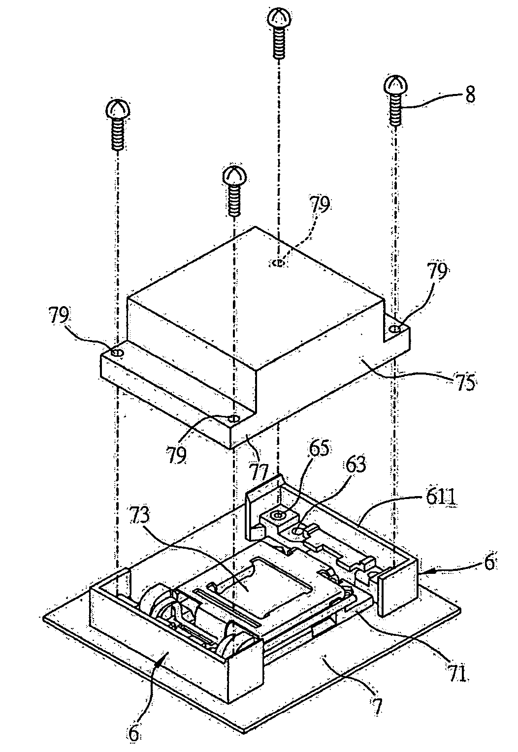
[0028] Referring to FIGS. 3 and 4, a three dimensional view and a cross-sectional view of a fastening device for heat sinks of the present invention are shown, respectively. As shown, the fastening device 6 of the present invention comprises a body 61, a positioning portion 63 disposed at the bottom of the body 61, and a spiral fastening portion 65 provided on the body 61.

[0029] In this embodiment, the body 61 is for example a plastic body and can be disposed on an installing face of a motherboard. An outer frame 611 is vertically provided on the top of the body 61. The outer frame 611 extends upwards from the outer face of the body 61 and has a “n” shaped cross section. This outer frame 611 can be used to frame a side of a base of a heat sink, so the size of the outer frame 611 is designed according to the hea...


PUM


Abstract

A fastening device for a heat sink, for being combined to each of two sides of a base of the heat sink for fastening the heat sink on an installing face is disclosed, wherein the two sides of the base respectively include jointing holes. The fastening device has at least a body, a positioning portion provided at the bottom of the body and a spiral fastening portion provided on the body to be combined with the base via spiral fastening components. Since the heat sink can be fastened via two of the fastening devices in conjunction with the spiral fastening components, problems in the prior art, such as complicated structure, excessive amount of components used and extra usage space required, can be solved.

Description

FIELD OF THE INVENTION [0001] The present invention relates to a design of a fastening device, and more particularly, to a fastening device for fastening a heat sink to an installing face. BACKGROUND OF THE INVENTION [0002] Following the revolution of integrated circuit related technologies, various kinds of power chips are developed towards the goals of miniaturization and high integration. However, this inevitably elevates the working temperature of the chips. Thus, heat dissipation is an extremely important issue in applications of the power chips. [0003] Heat sink modules are commonly equipped in chips, such as the CPU, the south bridge chip, and the north bridge in a motherboard. These heat sink modules varies according to the working temperature of the chips to which they are applied. For example, heat sink modules applied in the south and north bridge chips usually include only one heat sink, while heat sink module applied in the CPU usually includes a heat sink and a fan. Re...

Claims


Application Information

Patent Timeline
IPC IPC(8): H05K7/20G06F1/16H01L23/40H05K7/12
CPCH01L23/4006H01L2023/405H01L2023/4062H01L2023/4087H01L2924/0002H01L2924/00
Inventor YEH, YUN-CHIEH
Owner INVENTEC CORP
Learn More