
Bone abrading ultrasonic horns

Active Publication Date: 2006-10-19
INTEGRA LIFESCI IRELAND
View PDF15 Cites 47 Cited by
  • Summary
  • Abstract
  • Description
  • Claims
  • Application Information

AI Technical Summary

Benefits of technology

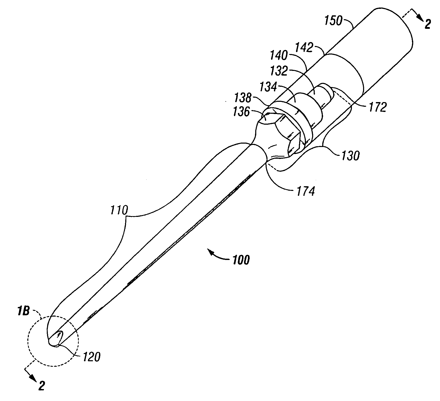
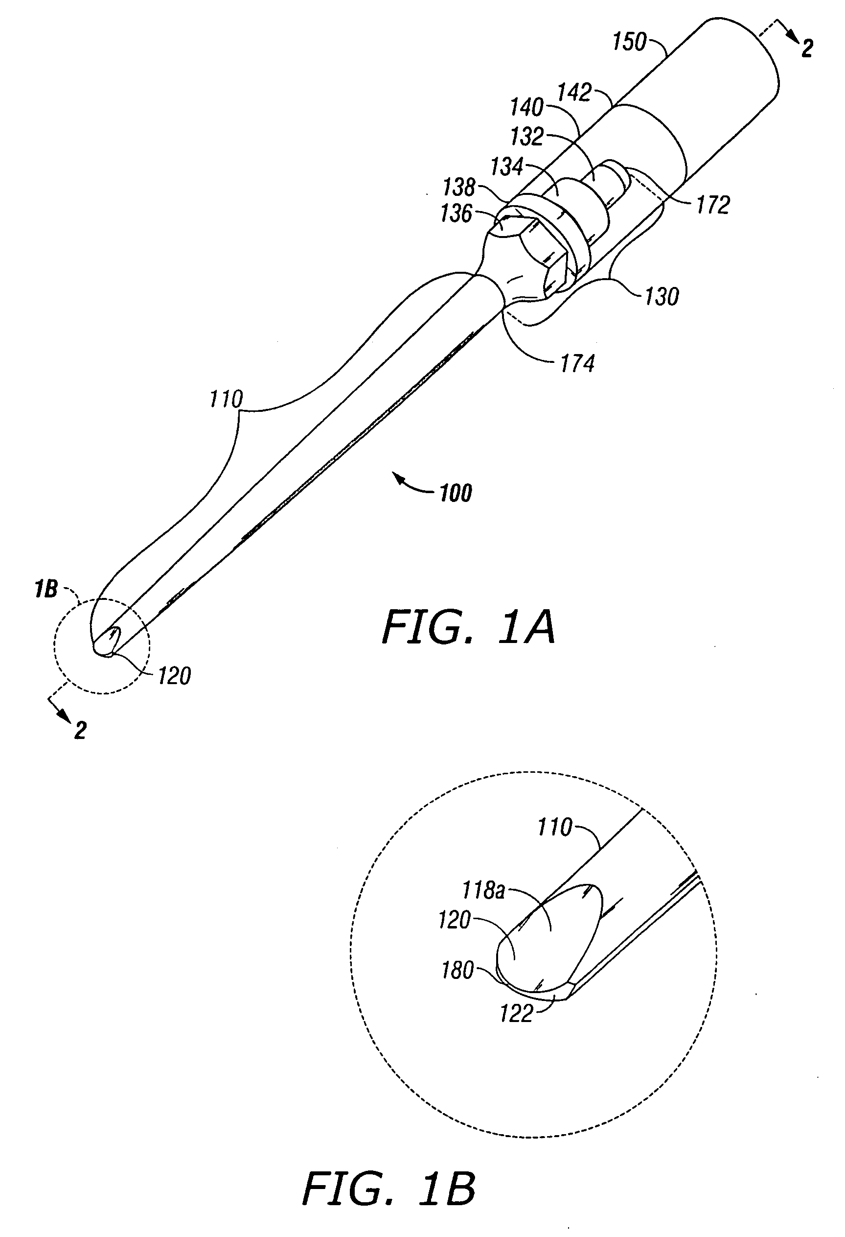
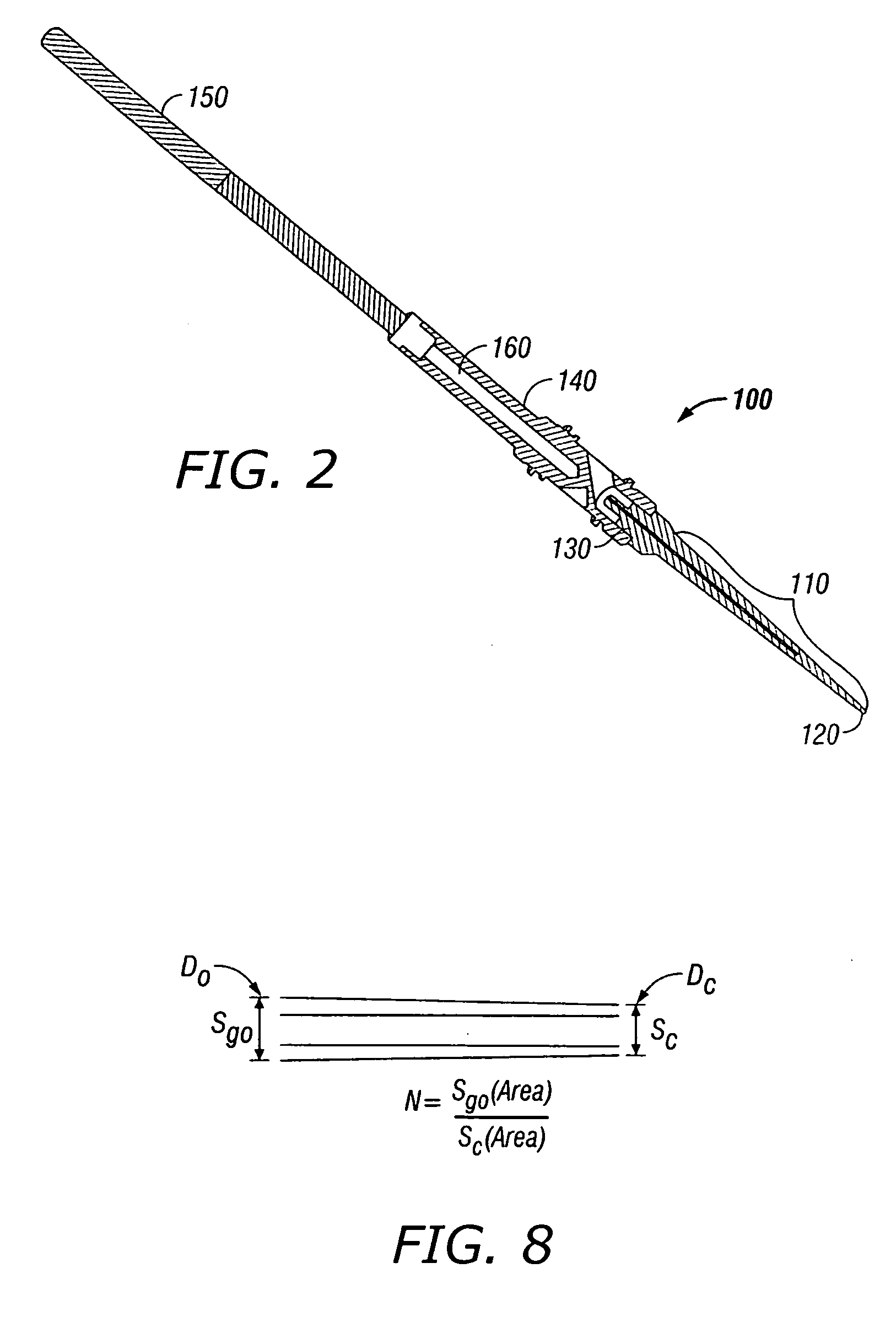
[0016] In accordance with the present invention, an ultrasonic horn is provide which is configured to remove bone in a controlled manner. The ultrasonic horn of the present invention provides reserve power that is far greater than is needed to readily cut or abrade bone.

Problems solved by technology

Certain limitations have emerged in attempts to use such devices in a broad spectrum of surgical procedures.
For example, the action of a continuously vibrating tip may not have a desired effect in breaking up certain types of body tissue, bone, etc.
Because the ultrasonic frequency is limited by the physical characteristics of the handheld device, only the motion available at the tip provides the needed motion to break up a particular tissue.
In any case, the devices have limitations in fragmenting some tissues.
The limited focus of such a device may render it ineffective for certain applications due to the vibrations which may be provided by the handheld device.
However, changes in operational parameters, such as changes in temperature, thermal expansion and load impedance, result in deviations in the resonant frequency.
A surgeon manipulates the handpiece manually at an operative site, and therefore, the handpiece itself may reduce visibility of the operative site.

Method used


Image

  • Bone abrading ultrasonic horns
  • Bone abrading ultrasonic horns
  • Bone abrading ultrasonic horns

Examples


example

[0105] In one embodiment of horn 100, as indicated in FIG. 15, a 23 kHz resonant frequency titanium tip lead 120 of the profile discussed was developed to match the design frequency fi of the existing CUSA™ transducer. FIG. 15 illustrates the benefits of being able to transfer models to automated contouring machine practices, wherein the results of modeling of the area function of the Gaussian and associated outside diameters, D, and internal hole diameters, d, are provided. In particular, the following diameters are shown in FIG. 15 and in the associated table of data: (a) Dgo is the outer diameter of elongated member 110 along hollow portion 112, which varies as a function of x, in inches; (b) dg is inner diameter of hollow portion 112 of elongated member 110 and is substantially constant.

[0106] A particular benefit of the mathematical approach to the profile, which includes the wall defined by the Gaussian and channel, the decaying exponential solid, and tangent function of the ...


PUM


Abstract

Ultrasonic horns configured for use with a surgical ultrasonic handpiece including a resonator are described. The ultrasonic horns include an elongated member having a longitudinal internal channel extending therethrough. Disposed on the distal end of the elongated member is a tip lead configured for cutting and / or abrading hard tissue, for example bone. The tip lead includes an abrasive surface.

Description

CROSS-REFERENCES TO RELATED APPLICATIONS [0001] This application claims priority to U.S. Provisional Patent Application Ser. No. 60 / 748,826 entitled Ultrasonic Horns, filed Dec. 9, 2005, and U.S. Provisional Patent Application Ser. No. 60 / 671,739 entitled Ultrasonic Horns, filed Apr. 15, 2005 the entirety of which are incorporated herein by reference.BACKGROUND OF THE INVENTION [0002] 1. Technical Field [0003] This disclosure relates to surgical systems and, more particularly, to ultrasonic horns for fragmenting tissue during a surgical procedure. [0004] 2. Background of Related Art [0005] Devices which effectively utilize ultrasonic energy for a variety of applications are well-known in a number of diverse arts. The Ampulla (Gaussian) profile was published by Kleesattel (as early as 1962), and is employed as a basis for many ultrasonic horns in surgical applications including devices patented and commercialized by Cavitron and Valleylab (patents by Wuchinich, et al, 1977, Stoddard,...

Claims


Application Information

Patent Timeline
IPC IPC(8): A61B8/14
CPCA61B17/1604A61B17/1659A61B2017/320076A61B17/320068A61B2017/320072A61B17/1688A61B2017/32007A61B2017/320075A61B2017/320078A61B2017/320089
Inventor COTTER, DANIEL J.BENSON, MARIASHINOPULOS, MATTHEWO'CONNOR, JAMES P.
Owner INTEGRA LIFESCI IRELAND
Learn More