Well Pump Controller Unit

Inactive Publication Date: 2006-10-19
GUION WALTER FRANKLIN
View PDF5 Cites 68 Cited by
  • Summary
  • Abstract
  • Description
  • Claims
  • Application Information

AI Technical Summary

Benefits of technology

[0002] The current invention is a controller device used to continuously control and optimize oil production from a well. The current invention is used in conjunction with a precise well measuring device, i.e. a device that can precisely measure charact

Problems solved by technology

As further described in Guion et al., the acoustic sounding method has not been able to reach its

Method used


Image

  • Well Pump Controller Unit
  • Well Pump Controller Unit
  • Well Pump Controller Unit

Examples


Embodiment Construction

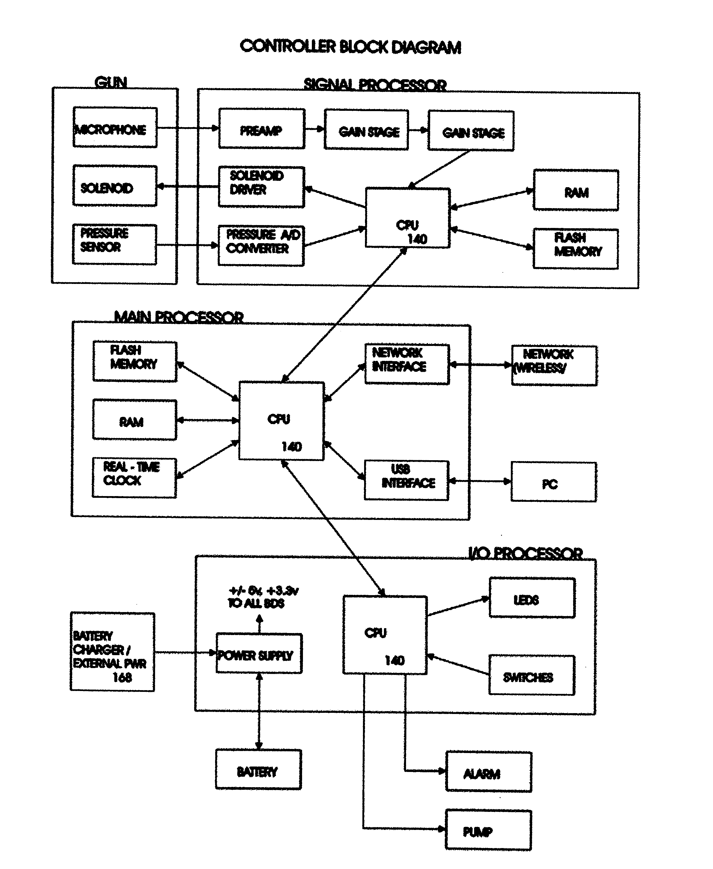
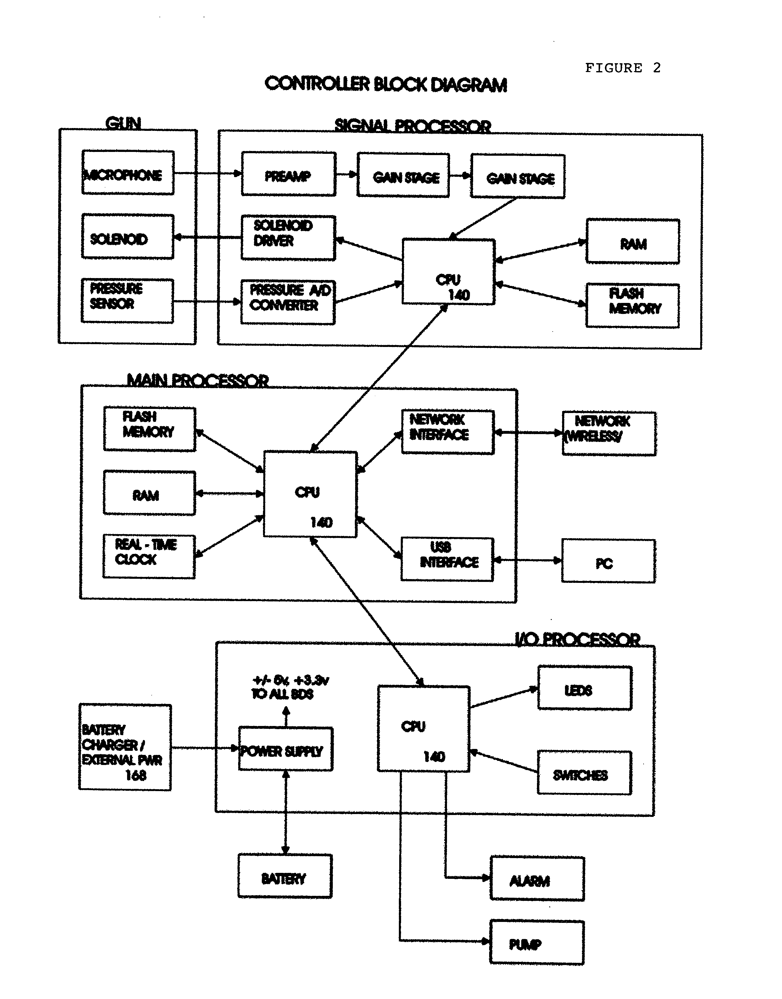
[0009] In the preferred embodiment of the current invention described herein the Controller Unit 200 is used with an Acoustic Generator 0 as described in Guion et al. As shown in FIG. 1, the following describes the components and operations of the Controller Unit 200 in a preferred embodiment of the current invention.

[0010] In a preferred embodiment of the current invention there are two input signals to, and one output signal from, the Controller Unit 200 to an Acoustic Generator 0. The analog signals from the Acoustic Generator Pressure Transducer 77 are digitalized by the Controller Unit 200 using an A / D Converter 134 for processing by the Controller Unit CPU 140. The analog signal from the Acoustic Generator Microphone 34 is sent to a Preamp 130 and two Gain Stages 136 and 138 in the Controller Unit 200 for input to the CPU 140 where it is digitalized by an A / D converter inside the CPU 140. There are two gain stages to maximize the signal and minimize gain errors although more ...


PUM


Abstract

In the oil production industry one objective of the field operator is to streamline their oil pumping operations for the more efficient production. The current invention is a controller device used to continuously control and optimize oil production from a well. The current invention is used in conjunction with a precise well measuring device, i.e. a device that can precisely measure characteristics of a well at a moment in time, for generating real-time information to be used by the controller device to optimize the rate of oil production.

Description

BACKGROUND OF THE INVENTION [0001] As described in U.S. patent application Ser. No. 10 / 907,611. “Acoustic Generator for Distance Sounding”, Guion et al. (hereinafter incorporated by reference and referred to as “Guion et al.”) the acoustic sounding method is one of several methods used in the oil industry to measure and analyze the fluid depth and other characteristics of an oil well. As further described in Guion et al., the acoustic sounding method has not been able to reach its true potential in oil production because of the lack of automation in these well measuring devices. One potential use of the acoustic sounding method that has not been employed to date is in the area of automated production, i.e. its use and application in real-time oil production situations in order to provide optimum oil production from a well. BRIEF SUMMARY OF INVENTION [0002] The current invention is a controller device used to continuously control and optimize oil production from a well. The current i...

Claims


Application Information

Patent Timeline
IPC IPC(8): G05D7/00
CPCF04B47/06
Inventor GUION, WALTER FRANKLIN
Owner GUION WALTER FRANKLIN
Why Eureka
Try Eureka