[0009]In conventional liquid-liquid extraction and coalescing processes involving large drops of oil (greater than 1,000 microns), the mixing and separation of the oil and water phases by a dispersive process is routinely practiced with relative ease. However, when the oil drops are significantly smaller in
diameter (less than 10 microns) and solids are present, the complete separation of the immiscible liquids is extremely difficult, if not impossible using dispersive methods routinely practiced for larger oil droplets. When routine methods are applied to try to recover small oil droplets from water in the presence of solids (such as cells or
cell debris), a
solid-liquid-liquid
emulsion layer is created resulting in an incomplete and inefficient separation of the two liquids. Therefore a new process is required that will allow for a more efficient separation and
elimination of the
solid-liquid-liquid-
emulsion problem. The process of the present invention enables the recovery of micron and submicron sized insoluble oil drops from an aqueous
slurry utilizing a novel non-dispersive process.
[0010]A non-dispersive process promotes a one-way flow of specific compounds into and through a membrane to remove the compounds from the shell side feed to the tube side. A non-dispersive
separation process is currently used to remove dissolved gases from liquids such as the removal of dissolved
oxygen from water to produce ultra pure water for the
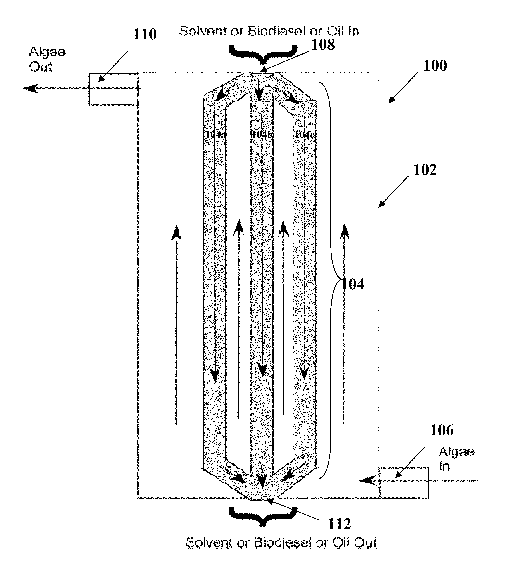
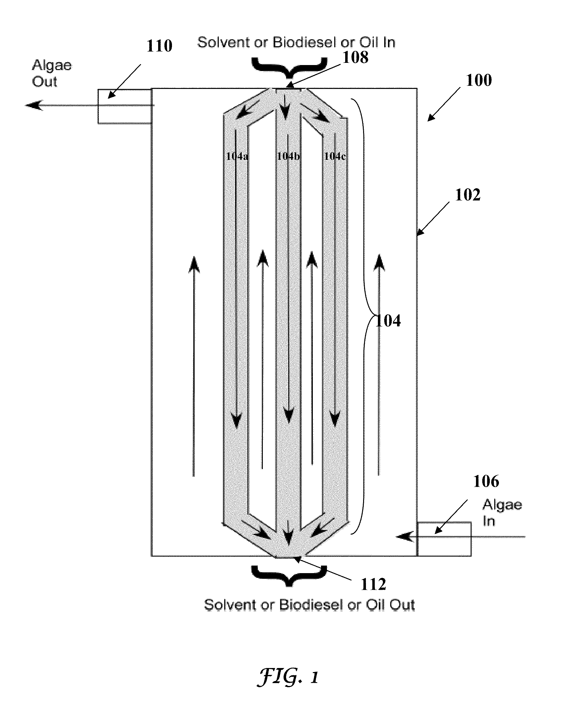
microelectronics industry. The present invention is a first successful demonstration of the application of non-dispersive processes to recover insoluble oil from water or aqueous slurries. The non-dispersive process disclosed herein uses a microporous
hollow fiber membrane composed of hydrophobic fibers. The aqueous slurry containing the insoluble oil is fed on the shell-side of the hollow
fiber module and a
hydrocarbon-appropriate solvent, for example, a
biodiesel, or similar oil recovered in previous application of the described process is fed on the tube side of the hollow
fiber module as a collection fluid. The aqueous phase passes around the outside of the large surface area of hydrophobic fibers containing the hydrophobic collection fluid as it passes through and eventually out of the module. As the aqueous liquid with the insoluble oil drops passes through the module, the insoluble oil droplets coalesce on to the walls of hydrophobic fibers and dissolve into the
hydrocarbon-appropriate collection fluid on the tube side of the module and are carried out of the module with the collection fluid. In this process, the tube side collection fluid does not make prolonged contact with the aqueous phase or disperse into the aqueous phase. The absence of this mixing as hypothesized by the inventors prevents the formation of a solid-liquid-liquid emulsion, when solids were present, allowing insoluble oil to be recovered efficiently from an aqueous slurry containing solids. The above
hypothesis was successfully demonstrated herein to efficiently recover insoluble oil from an aqueous mixture including cells without the formation of a solid-liquid-liquid emulsion.
[0012]The novel extraction process of the present invention utilizes a non-dispersive
solvent extraction method to coalesce and recover an insoluble oil from an aqueous slurry. As an example, the recovery of non-polar algal oil from an algal concentrate is described. The technique utilizes a microporous
hollow fiber membrane contactor. The inventors have tested the Liqui-
Cel Extra Flow
Contactor, commercially used for gas / liquid contacting, to obtain >80% extraction efficiency and process concentrates up to 10% bio-cellular solids without
membrane fouling. The
novel technique of the present invention utilizes the large coalescing area provided by the surface of the microporous hollow fibers when filled with a hydrophobic collection fluid and minimizes the actual contact of the solvent with the (e.g.
algae)
biomass and aqueous phase.
[0013]The novel extraction process described herein can be coupled with a variety of appropriate collection fluids for recovery of insoluble compounds, depending upon the types of compound or compounds to be recovered. The choice of collection fluid will
impact both the sub-set of compounds recovered from the aqueous slurry as well as the downstream steps needed to economically and efficiently use compounds from the collection fluid. Differential extraction of desired molecules, for example, recovery of non-polar oils, but not polar oils, can be achieved by choice of collection fluid. Segregation of non-polar oils from polar oils, specifically polar oils containing phosphorous (e.g., phospholipids), is highly advantageous as
phosphorus containing compounds complicate both the refining and
transesterification processes used to create transportation fuels. Polar oils could be recovered using the process described herein using a different collection fluid, for example as a secondary recovery step once non-polar oils are already removed.
[0014]Downstream steps needed to recover desired molecules from the collection fluid are also
application specific. If
heptane is used as the collection fluid, compounds of interest may be recovered by
distillation without the need of a steam stripper. If biodiesel (
Fatty Acid Methyl Ester [FAME]) is used as the collection fluid, e.g., recovered oils may not require
processing prior to
transesterification to FAME. Importantly, the present invention can also use a “self” oil that has been previously extracted from an aqueous slurry as the collection fluid thereby completely eliminating the need and expense of having to separate the recovered compounds from the collection fluid. In this application, the collection fluid is a quantity of oil derived from a previously processed aqueous slurry or extracted by a different method. The microporous hollow fiber
membrane contactor as described in the present invention is small, portable, economical and is capable of handling large aqueous slurry feed rates.

