
Apparatus and method for performing time delay estimation of signals propagating through an environment

a time delay estimation and environment technology, applied in the field of signal processing, can solve the problems of low signal-to-noise ratio (snr), the effect of reducing the accuracy of sonar ranging, and the inability of the correlator to produce accurate range measurements, so as to increase the accuracy of time delay estimation

Inactive Publication Date: 2006-10-19
BROWN UNIVERSITY
View PDF12 Cites 12 Cited by
  • Summary
  • Abstract
  • Description
  • Claims
  • Application Information

AI Technical Summary

Benefits of technology

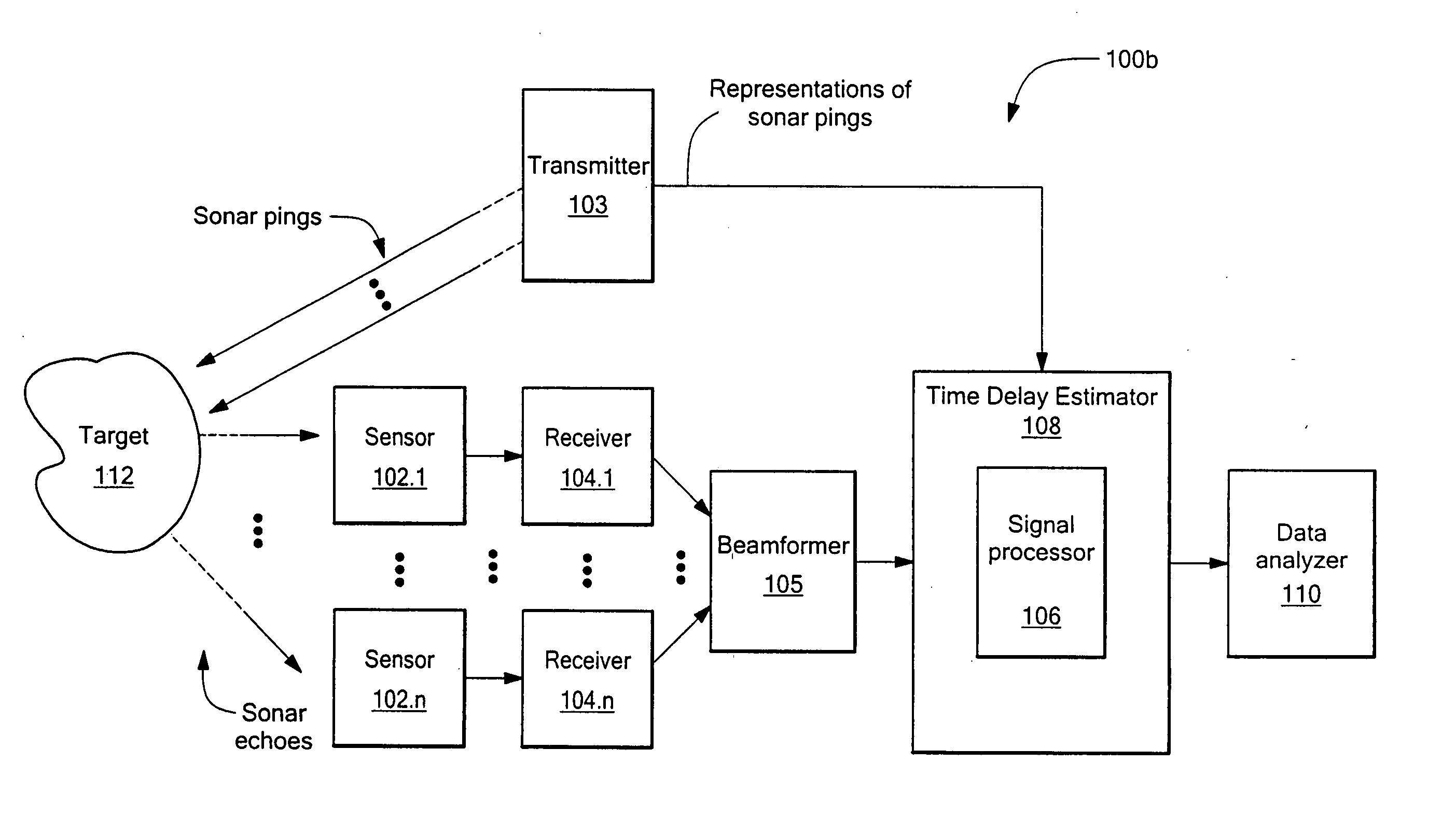
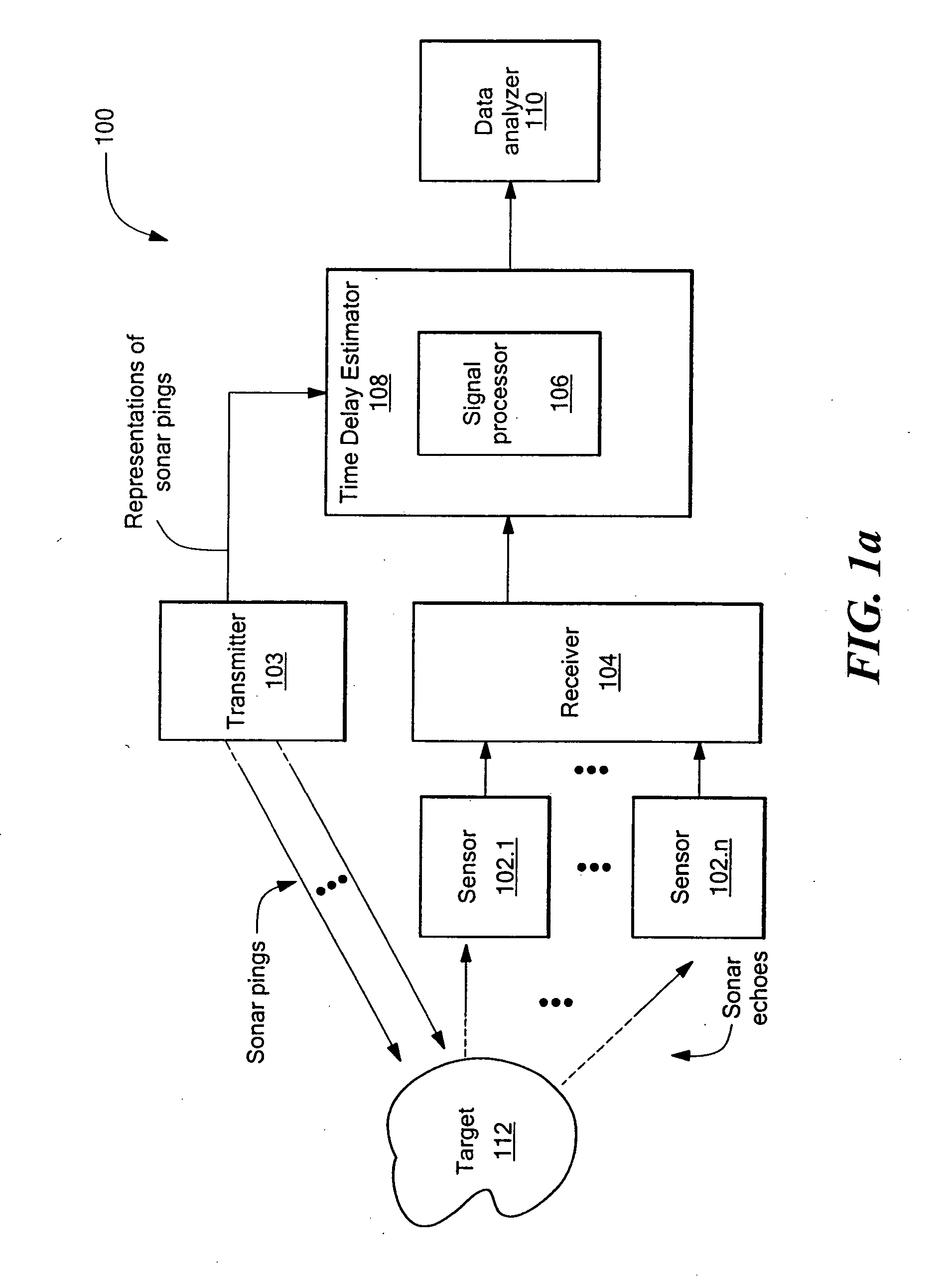
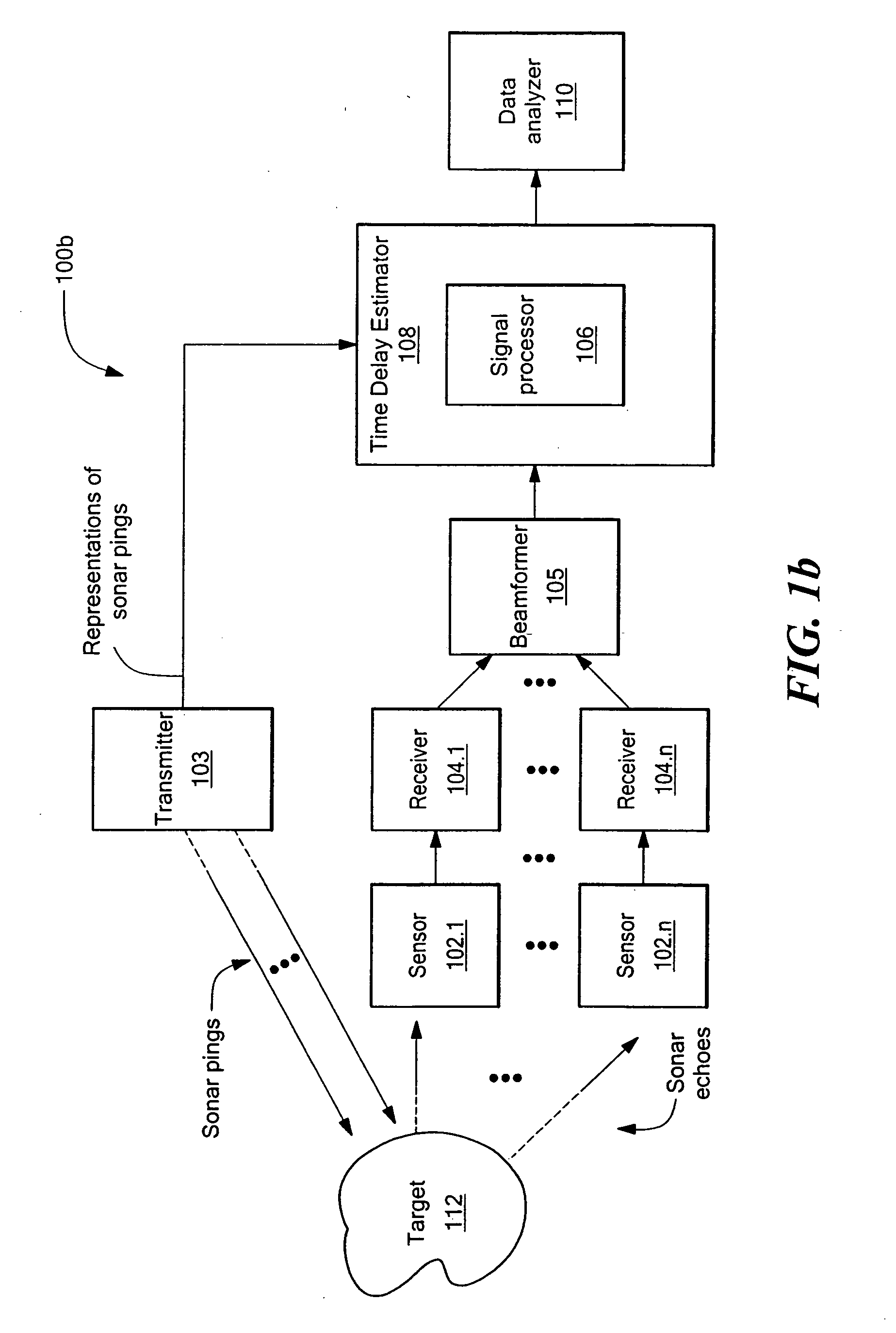
The present invention provides a system and method for improving the accuracy of time delay estimates of signals propagating through an environment. This is achieved by using multiple transmitted or received signals, where at least some of the noise is non-correlated. The system measures the time delays between multiple pairs of signals and analyzes the data to generate a statistical distribution of the time delay estimates. By increasing the number of signals and calculating the mean, median, or mode of the distribution, the accuracy of time delay estimation is increased and noise tolerance is improved. The system can be used in various fields such as sonar, seismic, ultrasonic, acoustic, or electromagnetic signals.

Problems solved by technology

Such reflected sonar pulses (“echoes” or “returns”) may include a significant amount of background noise and / or other interfering signals in addition to the reflected sonar signals of interest.
One drawback of the above-described conventional sonar system is that the level of background noise and / or other interfering signals contained within the echo or return may be sufficient to cause the reflected sonar signal to go undetected or to be falsely detected, thereby causing the cross correlator to produce inaccurate range measurements.
Such inaccurate range measurements are likely to occur in low signal-to-noise ratio (SNR) sonar environments, in which the noise power within the echo may be comparable to or greater than the reflected signal power.
This can be problematic in sonar ranging systems because a reduction in the measurement accuracy of the cross correlator typically leads to a concomitant reduction in sonar ranging accuracy.
However, such attempts have generally not worked well enough to allow successful detection of reflected sonar signals and accurate estimation of range in low SNR sonar environments.
Further, other ships, submarines, or structures producing noise across wide frequency ranges may be within the vicinity of the sonar system.
Moreover, the natural interaction of the water and objects within the water including the selected target may produce a substantial amount of ambient noise.
Further, at least some of the background noise may result from reverberations and / or random signal distortions of the ping and / or echo, and therefore the noise level and its structure may be significantly affected by the transmitted sonar signal.
However, conventional sonar systems are generally incapable of accurately estimating noise levels and target ranges in the presence of non-stationary, nonlinear, non-additive, and / or signal-dependent noise.
Moreover, the density and temperature of the transmission medium (e.g., water) and the frequency of the transmitted / reflected sonar signals may affect the decay rate of the sonar pulse propagating through the medium.
In addition, the absorption of certain frequencies of the ping by the target may affect the strength of the resulting echo.
However, conventional sonar systems are generally incapable of fully compensating for such factors when called upon to generate accurate noise and range estimates.

Method used


Image

  • Apparatus and method for performing time delay estimation of signals propagating through an environment
  • Apparatus and method for performing time delay estimation of signals propagating through an environment
  • Apparatus and method for performing time delay estimation of signals propagating through an environment

Examples


first embodiment

It is noted that the bound on the probability expressed in equation (32) is equal to the bound on the probability expressed in equation (27) for a single ping, thereby indicating that the bound on the probability α does not change with the number of pings. For this reason, taking the mean of the distribution of echo delay estimations, as described above with reference to the presently disclosed sonar system, generally does not improve the noise tolerance of the system, even though the accuracy of echo delay estimation is improved.

[0076] The method of the second embodiment of the sonar system 100 (see FIG. 1a) increases the accuracy of echo delay estimation and improves the noise tolerance of the system via a calculation of the mode of the distribution of echo delay estimates derived from multiple pings. As depicted in FIG. 12, the a priori window of the cross correlation may be divided into a total of m=└2 L / Δ┘ intervals B1, B2, . . . , Bm, in which B1=IΔ represents the correct bin....


PUM


Abstract

A system and method for increasing the accuracy of time delay estimates of signals propagating through an environment. The system includes one or more sensors for receiving a plurality of signals, and a time delay estimator for measuring time delays between multiple pairs of signals. At least some of the multiple pairs of signals are received and measured at different points in time. The system further includes a data analyzer for analyzing time delay estimation data, for generating a statistical distribution of time delay estimates from the data, and for calculating a statistical estimate of time delay from the distribution. By increasing the number of signals employed by the system, the accuracy of the time delay estimation is increased. Further, by calculating the median or the mode of the statistical distribution, noise tolerance is improved. The signals employed by the system may include sonar signals, seismic signals, ultrasonic signals, acoustic signals, electromagnetic signals, or any other suitable type of signals.

Description

CROSS REFERENCE TO RELATED APPLICATIONS [0001] This application claims priority of U.S. Provisional Patent Application No. 60 / 494,358 filed Aug. 12, 2003 entitled ECHO DELAY ESTIMATES FROM MULTIPLE SONAR PINGS.STATEMENT REGARDING FEDERALLY SPONSORED RESEARCH OR DEVELOPMENT [0002] This invention was made with government support under U.S. Government Contract Nos. ARO DAAD 19-02-1-0403 and ONR N00012-02-C-02960. The government has certain rights in the invention.BACKGROUND OF THE INVENTION [0003] The present application relates generally to signal processing, and more specifically to systems and methods of increasing the accuracy of time delay estimates of signals propagating through an environment. [0004] Various industrial and scientific techniques require accurate estimations of time delays of signals propagating through an environment such as an underwater environment, a soil environment, or an environment comprising living tissue. For example, in an underwater environment, sonar ...

Claims


Application Information

Patent Timeline
Patent Type & Authority Applications(United States)
IPC IPC(8): G06F19/00
CPCG01S7/5273H04L67/125G01V1/28
Inventor INTRATOR, NATHANKIM, KI-ONERETTI, NICOLACOOPER, LEON N.
Owner BROWN UNIVERSITY
Learn More