
Logic circuit design method, computer-readable recording medium having logic circuit design program stored therein, and logic circuit design device

a logic circuit and logic circuit technology, applied in the field of logic circuit design methods, can solve the problems of not revealing a function for moving instances in other ways, unable to apply, and only having limited functions of cad tools, so as to improve design convenience, facilitate and surely

Inactive Publication Date: 2006-10-19
FUJITSU LTD
View PDF4 Cites 2 Cited by
  • Summary
  • Abstract
  • Description
  • Claims
  • Application Information

AI Technical Summary

Benefits of technology

[0010] A general object of the present invention is to provide a logic circuit design method, a computer-readable recording medium having a logic circuit design program stored therein, and a logic circuit design device. A specific object of the present invention is to provide a logic circuit design method, a computer-readable recording medium having a logic circuit design program stored therein, and a logic circuit design device that allow automatic hierarchy reconstruction with use of CAD tools or the like, thereby reducing TAT (Turn Around Time), preventing errors due to manual corrections, and improving design quality and convenience.
[0012] With this method, operations required when moving an instance across blocks can be easily and surely performed with a simple configuration.
[0013] Accordingly, the present invention allows automatic hierarchy reconstruction for a circuit having a hierarchical structure in logical deign, thereby improving convenience in design, reducing TAT, and improving quality of circuit design.

Problems solved by technology

However, in some cases, logical design is made different from physical design because of CAD tool operability or designers convenience.
However, it does not disclose a function for moving instances in other manners different from the manner described above with reference to FIG. 1 or a function for deleting hierarchical ports that have become unnecessary during a reconstruction operation.
This technique is applicable when two pins or ports are connected to a net, but it seems to be not applicable when three or more pins or ports are connected to a net.
Because existing CAD tools only have limited functions for hierarchy reconstruction as described above, designers need to manually reconstruct hierarchy or perform complicated operations for hierarchy reconstruction using the existing CAD tools.

Method used


Image

  • Logic circuit design method, computer-readable recording medium having logic circuit design program stored therein, and logic circuit design device
  • Logic circuit design method, computer-readable recording medium having logic circuit design program stored therein, and logic circuit design device
  • Logic circuit design method, computer-readable recording medium having logic circuit design program stored therein, and logic circuit design device

Examples


Embodiment Construction

[0043] Specific examples of logical hierarchy reconstruction processing performed by a logical hierarchy reconstruction method according to the present invention are given below with reference to FIGS. 1-4.

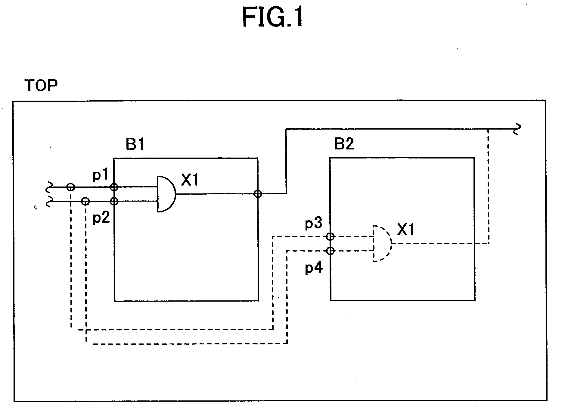
[0044]FIG. 1 illustrates a part of logic circuit design data having a hierarchical structure. A logic circuit shown in FIG. 1 comprises a top block TOP, and blocks B1 and B2 one level below the block TOP. FIG. 1 shows processing for moving a cell X1 as a logic element from the block B1 to the block B2. In this case, when the cell X1 is moved from the block B1 to the block B2, hierarchical ports p1 and p2 become unnecessary and therefore need to be deleted from the source block B1. On the other hand, in the destination block B2, hierarchical ports p3 and p4 need to be newly created.

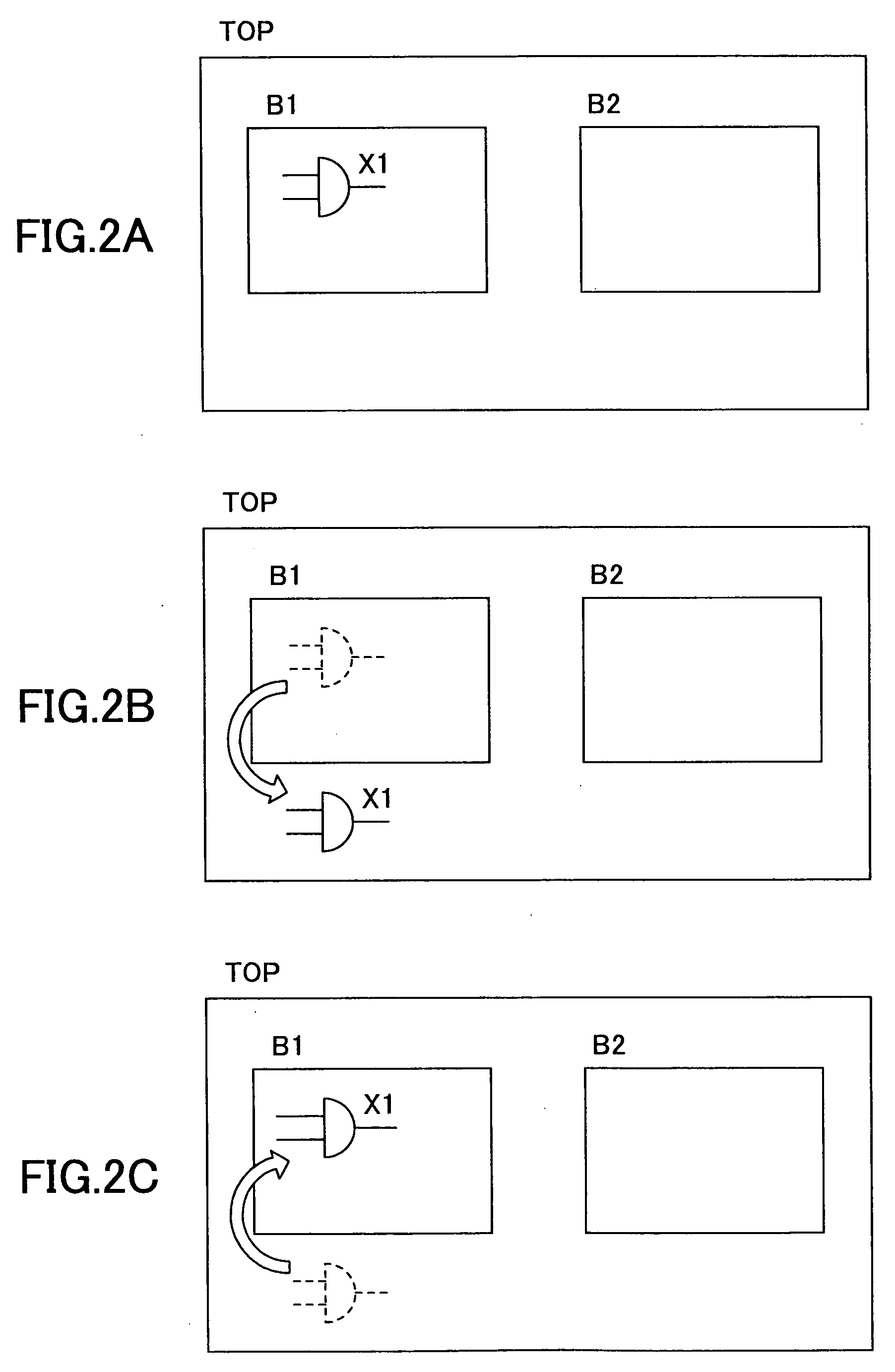
[0045]FIGS. 2A-2C illustrate an operations for moving a cell X1 from a block B1 to a block TOP one level above the block B1 (FIG. 2A→FIG. 2B), and the reverse operation (FIG. 2B→FIG. 2C).

[0046]FIG. 3 ...


PUM


Abstract

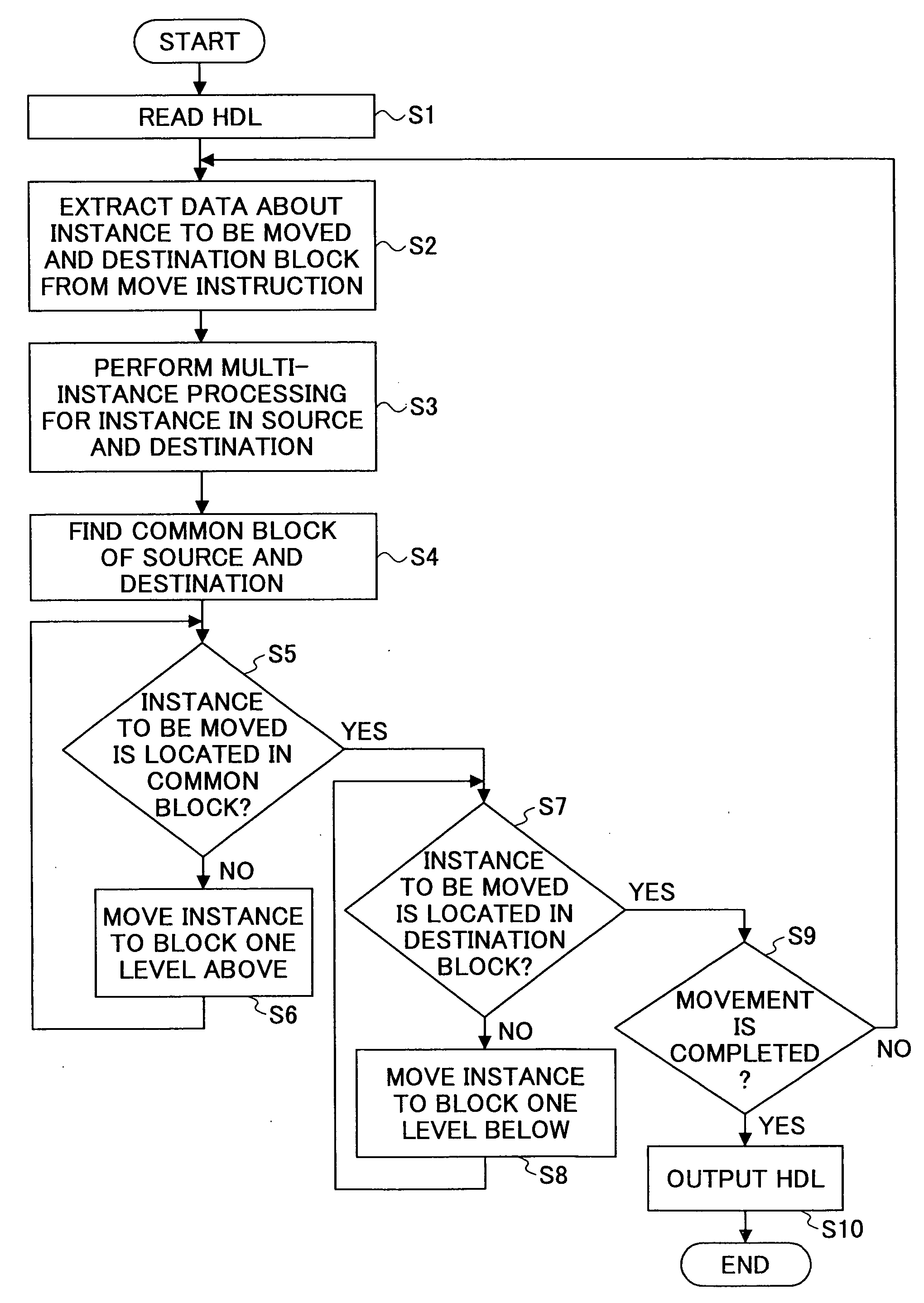
A logic circuit design method for use in a logic circuit having a hierarchical structure including an instance, a first block, and a second block is disclosed. The logic circuit design method includes the steps of reading information about the logic circuit, moving an instance which has a signal connection and a first hierarchical port connected thereto from a first block to a second block in accordance with the read information, creating a second hierarchical port in accordance with the movement of the instance, and disconnecting the instance from the first hierarchical port and connecting the instance to the second hierarchical port while maintaining the signal connection to the instance that the instance had at the time when the instance was moved from the first block to the second block.

Description

BACKGROUND OF THE INVENTION [0001] 1. Field of the Invention [0002] The present invention relates to a logic circuit design method, a computer-readable recording medium having a logic circuit design program stored therein, and a logic circuit design device, and particularly relates to a logic circuit design method, a computer-readable recording medium having a logic circuit design program stored therein, and a logic circuit design device that are applicable in logic circuit design using a hierarchical structure. [0003] 2. Description of the Related Art [0004] As LSI circuits have become larger and larger in recent years, the use of design techniques such as so-called hierarchical division and tiling have become mainstream in physical design or layout design (i.e. operations for determining arrangement of cells and wiring between cells) of LSI circuits. It is therefore preferable in logical design, which is a preliminary process of physical design, to design a logical hierarchy corre...

Claims


Application Information

Patent Timeline
Patent Type & Authority Applications(United States)
IPC IPC(8): G06F17/50
CPCG06F17/5045G01R31/318364G06F30/30
Inventor FURUKAWA, EIJI
Owner FUJITSU LTD
Learn More