Method for manufacturing headrest stay

a manufacturing method and headrest technology, applied in the field of headrest stays, can solve the problems of high equipment investment cost, pile collapse, transportation and damage, etc., and achieve the effects of reducing the thickness of the plated layer, excellent decoration property, and bending successfully

Inactive Publication Date: 2006-10-26
ARAI IND +1
View PDF12 Cites 14 Cited by
  • Summary
  • Abstract
  • Description
  • Claims
  • Application Information

AI Technical Summary

Benefits of technology

[0020] Further, in the plating step, by forming the linear-shaped metal pipe into a structure in which the thickness of the plated layer at the middle portion of the metal pipe which will be an embedded portion of the headrest stay is smaller than the plated layer of the vicinity of the opposite end portions of the metal pipe which will be inserted portions of the headrest stay, no cracks occur on the plated layers when the middle portion of the metal pipe is bent to create the embedded portions of the headrest main body, and the bending can be executed successfully.
[0021] Further, since a plated layer of a sufficient thickness can be formed in the vicinity of the opposite end portions of the metal pipe which will be the inserted portions of the headrest stay, even if the opposite end portions of the stay are in an exposed stat...

Problems solved by technology

In this case, however, there arises a problem that many pieces of equipment such as a cutting machine, plating processing equipment, and a bending machine, and high-level processing techniques are required, and therefore high equipment investment cost is required.
However, since a headrest stay is a three dimensional solid state formed by bending a metal pipe into the shape of substantially letter U, if headrest stays are packed in a simple package or are bound together simply, the piles of the headrest stays tend to collapse during the transportation and are damaged.
Therefore, the packaging and transportation of the headrest stays are difficult beyond expectations.
However, in the case where headrest stays are transported using the ded...

Method used


Image

  • Method for manufacturing headrest stay
  • Method for manufacturing headrest stay
  • Method for manufacturing headrest stay

Examples


Embodiment Construction

[0028] Hereinafter, the present invention will be described based on the embodiments shown in the drawings. It should be noted that the present invention is not limited to the embodiments, and various modifications within the matters of the claims and equivalents related to the matters of the claims are included in the scope of claims.

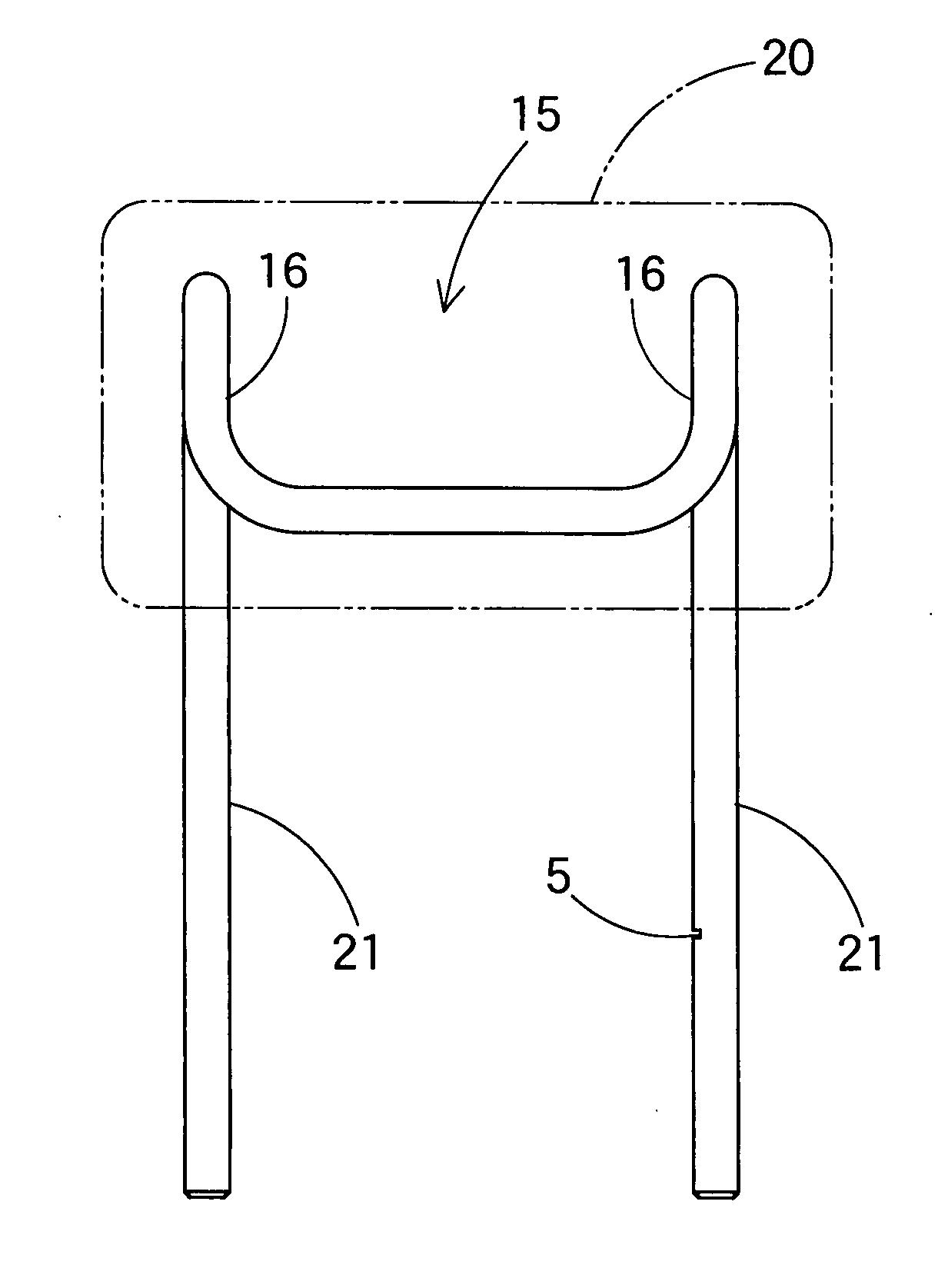
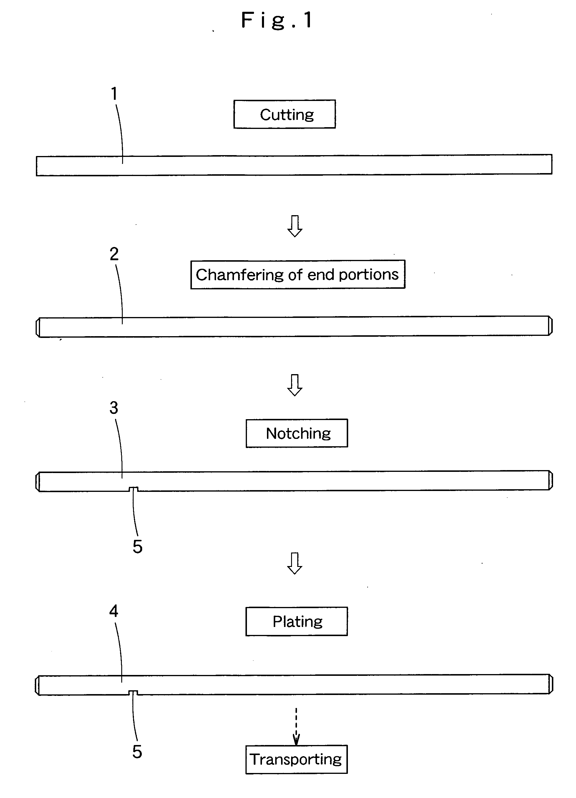
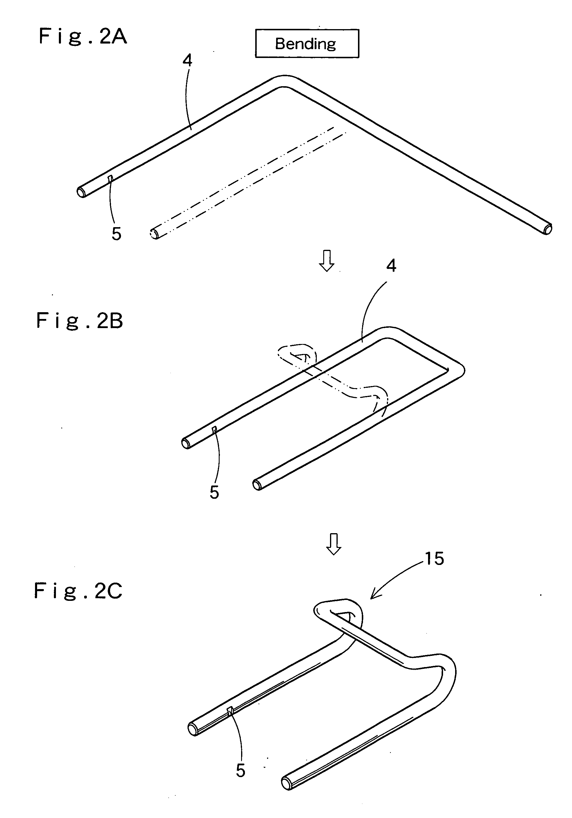
[0029]FIG. 1 shows a process diagram of a method for manufacturing a headrest stay. The headrest stay manufactured here is generally formed in the following steps. That is, a linear-shaped metal pipe is cut into a predetermined length, and the resultant linear-shaped metal pipe is plated on its surface, and after that, the plated metal pipe is bent into a predetermined shape substantially in the letter U.

[0030] As shown in FIG. 1, first of all, a metal pipe material is cut into a predetermined length to form a metal pipe 1. As the metal pipe material, for example, a high tensile steel pipe having a thickness of about 1.5 to 2.0 mm and an outer diamet...


PUM

PropertyMeasurementUnit
Thicknessaaaaaaaaaa

Abstract

The manufacturing method of the present invention is a method for manufacturing a headrest stay including an embedded portion to be embedded into a headrest main body, and inserted portions to be inserted into a top portion of a seat back integrally made of a metal pipe into one piece unit. This manufacturing method includes the steps of: cutting a linear-shaped metal pipe material into a predetermined length; chamfering end surfaces of the cut metal pipe; forming a notch at a predetermined position on an outer peripheral surface of the metal pipe; plating the surface of the linear-shaped metal pipe so as to form a plated layer after the chamfering and notch forming steps; and bending the plated metal pipe into the shape of the substantially letter U, wherein said bending step is executed after said plating step.

Description

FIELD OF THE INVENTION [0001] The present invention relates to a method for manufacturing a headrest stay which is used as a supporting member of a headrest to be mounted on a top portion of a seat back of a vehicle seat. DESCRIPTION OF THE RELATED ART [0002] Normally, a headrest is mounted on a top portion of seat back of a vehicle seat. The headrest generally includes a headrest main body including a pad molded from a foaming material and the like, and a headrest stay substantially in the shape of letter U which is embedded within the headrest main body and has opposite end portions protruding form the headrest main body (for example, see Japanese Patent Laid-Open Publication No. 2004-14959). [0003] Such a headrest stay to be used in the headrest is generally made of a metal pipe bent into the shape of substantially letter U. The metal pipe is chamfered at its end surfaces, and at the same time, is notched at its predetermined position, and further, is plated on its outer peripher...

Claims


Application Information

Patent Timeline
IPC IPC(8): B23P25/00B21B1/46B21D47/00
CPCB23P15/00B60N2/48Y10T29/49885Y10T29/49623Y10T29/49982B60N2/7017B60N2/80
Inventor ARAI, TOKUJI
Owner ARAI IND
Why Eureka
Try Eureka