Method for forming pattern and a wired board
a wired board and pattern technology, applied in the field of wired board and pattern formation, can solve the problems of large apparatus or equipment, high production cost, and certain limits, and achieve the effect of fine conductive pattern and easy formation of pattern
- Summary
- Abstract
- Description
- Claims
- Application Information
AI Technical Summary
Benefits of technology
Problems solved by technology
Method used
Image
Examples
first embodiment
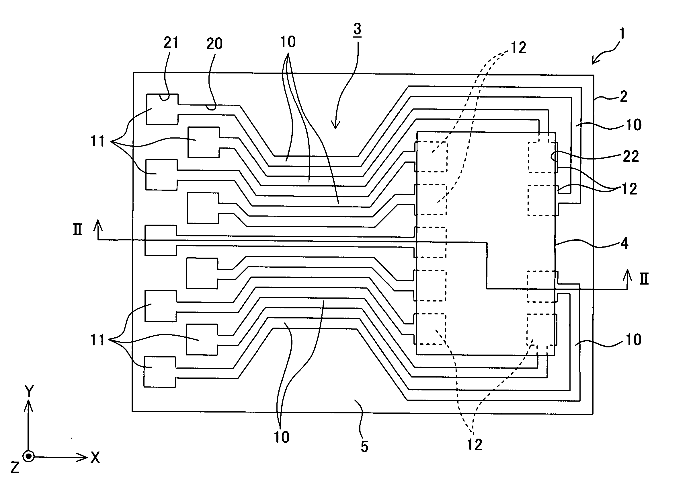
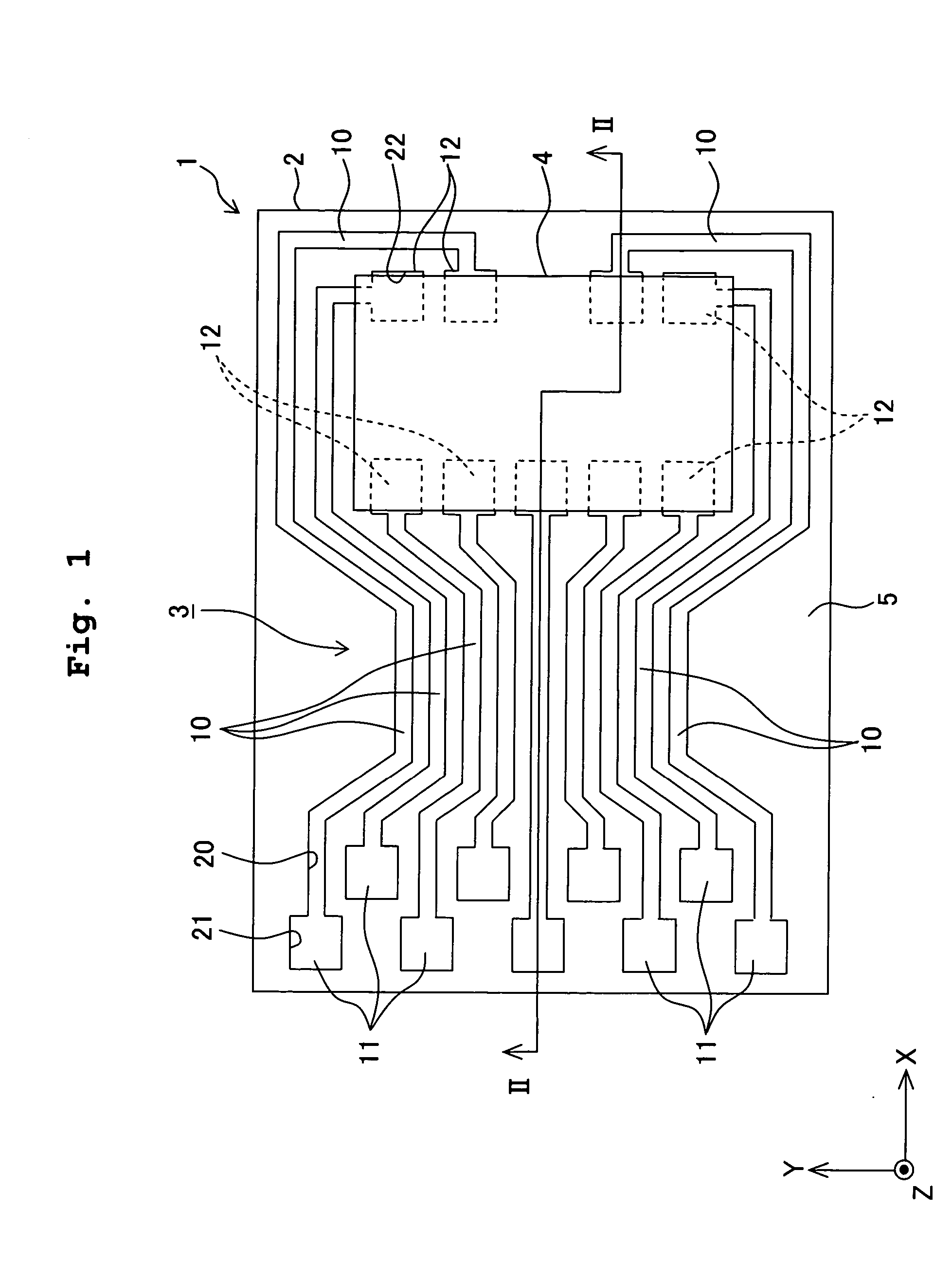
[0059] A first embodiment of the present invention will be explained. The first embodiment is an example of the application of the present invention to a case in which a conductive pattern is formed on a surface of a flat plate-shaped base material for constructing a board. The following description will be made assuming that the X axis direction shown in FIG. 1 is defined as the longitudinal direction or the left and right directions, and the direction (upward direction in FIG. 2), which is directed to the front side of the paper surface of FIG. 1 in the Z axis direction, is defined as the upward direction.
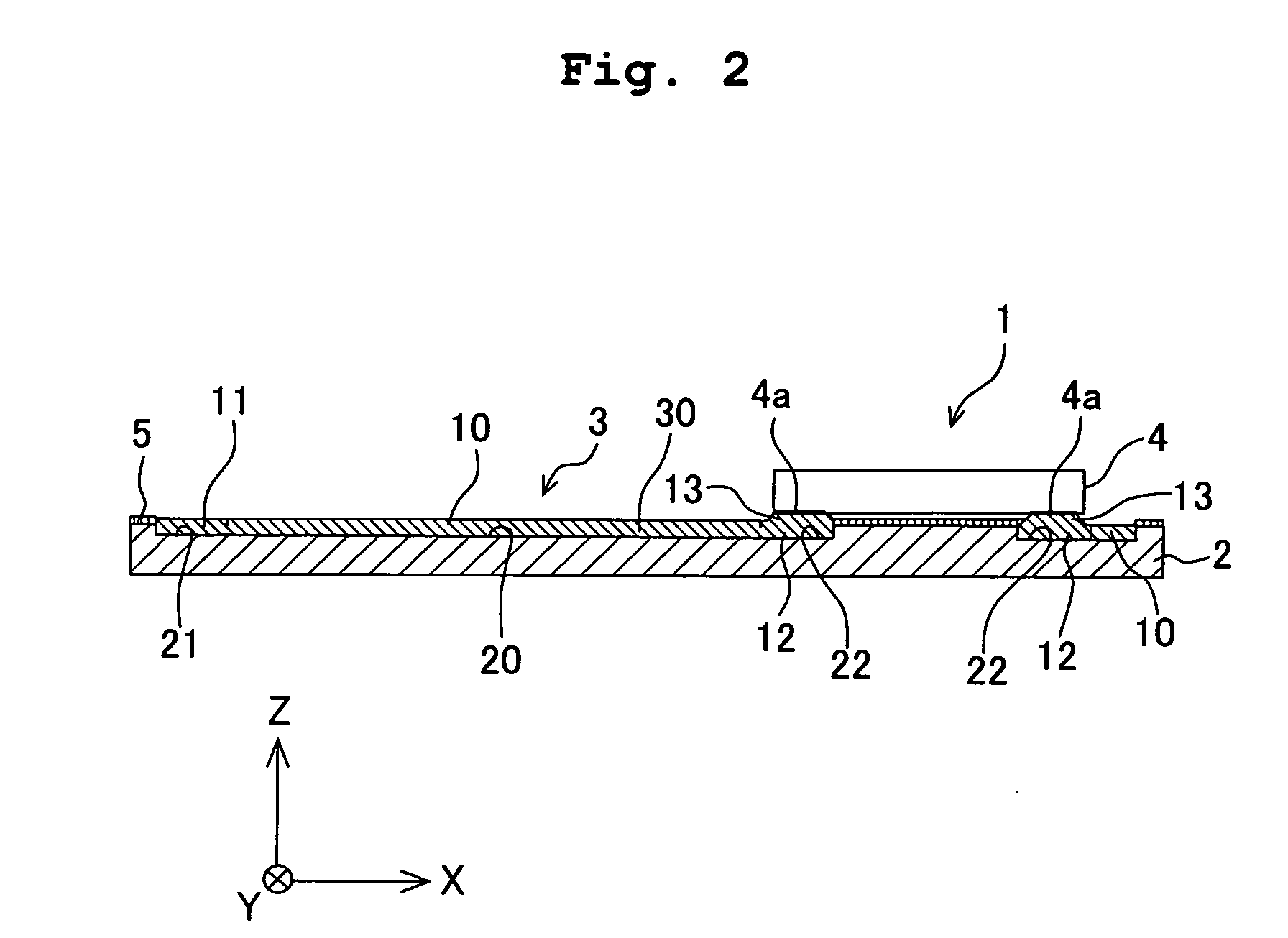
[0060] At first, the board 1 will be explained. As shown in FIGS. 1 and 2, the board 1 has the flat plate-shaped base material 2 which is composed of an insulating material, and the conductive pattern 3 which is formed on an upper surface of the base material 2. A driver IC 4 (electronic part), which serves as a driving circuit electrically connected to the conductive pattern 3,...
first modified embodiment
[0080] As shown in FIG. 5, surface layers 41 may be formed on the bumps 13 such that the bumps 13, which are composed of, for example, silver or gold, are formed on the surface of the conductive material 30 (connecting terminals 12) charged into the recesses 22, and then conductive liquid droplets, which contain a metal material such as melted solder different from the material of the bumps 13, are landed on the surfaces of the bumps 13.
second modified embodiment
[0081] It is not necessarily indispensable that the liquid-repellent film 5 is formed on the upper surface of the base material 2. It is also allowable that the liquid-repellent film-forming step is omitted. Also in this case, on condition that the surface roughness of the inner surface of the groove 20 and the recesses 21, 22 is larger than the surface roughness of the upper surface of the base material 2, the liquid repellence of the inner surface of the groove 20 and the recesses 21, 22 is lower than the liquid repellence of the upper surface of the base material 2. For example, when the groove 20 and the recesses 21, 22 are formed by means of the laser processing, then the inner surface for defining the groove 20 and the recesses 21, 22 can be made rough, and the wettability can be enhanced. In this case, the liquid repellence of the upper surface of the base material 2 is relatively higher than the liquid repellence of the inner surface of the groove 20 and the recesses 21, 22....
PUM
| Property | Measurement | Unit |
|---|---|---|
| width | aaaaa | aaaaa |
| width | aaaaa | aaaaa |
| volume | aaaaa | aaaaa |
Abstract
Description
Claims
Application Information
 - R&D
- Intellectual Property
- Life Sciences
- Materials
- Tech Scout
- Unparalleled Data Quality
- Higher Quality Content
- 60% Fewer Hallucinations
Browse by: Latest US Patents, China's latest patents, Technical Efficacy Thesaurus, Application Domain, Technology Topic, Popular Technical Reports.
© 2025 PatSnap. All rights reserved.Legal|Privacy policy|Modern Slavery Act Transparency Statement|Sitemap|About US| Contact US: help@patsnap.com


