Bioaerosol discrimination

a bioaerosol and discrimination technology, applied in the field of classification of particles, can solve the problems of false positive indications of fluorescence-based instruments and detectors still suffering from potential interference, and achieve the effect of promoting radiation emission

Inactive Publication Date: 2006-10-26
TIAX LLC
View PDF99 Cites 25 Cited by
  • Summary
  • Abstract
  • Description
  • Claims
  • Application Information

AI Technical Summary

Benefits of technology

[0010] In accordance with one or more embodiments, the present invention relates to a method of classifying an aerosol particle. The method can comprise measuring a composite emission decay profile of an emission from the aerosol particle, determining a biological fluorescence time constant of the composite emission decay profile, and determining a biological emission constant of the composite emission decay profile.
[0011] In accordance with one or more embodiments, the present invention relates to a method of classifying aerosol particles. The method can comprise stimulating the aerosol particles to promote radiation emission; measuring a composite emission decay profile of the radiation emission, the composite emission decay profile comprising a scatter component, a first fluorescence component, and a second fluorescence component; determining a scatter emission constant corresponding to the scatter component; determining a first fluorescence emission constant of the composite emission decay profile; and determining a second fluorescence emission constant of the composite emission decay profile.
[0012] In accordance with one or more embodiments, the present invention relates to a method of classifying an aerosol particle. The method can comprise measuring a composite emission from an aerosol particle, deconvolving the composite emission to determine a discriminant vector of the aerosol particle, and mapping the discriminant vector to provide an indication of the nature of the aerosol particle.
[0013] In accordance with one or more embodiments, the present invention relates to a method of characterizing an aerosol particle. The method can comprise acts of measuring a first composite emission decay profile of a first emission from the aerosol particle, measuring a second composite emission decay profile of a second emission from the...

Problems solved by technology

However, atmospheric pollutants may also fluoresce and can cause fluorescence-based instruments to register false positive ...

Method used


Image

  • Bioaerosol discrimination
  • Bioaerosol discrimination
  • Bioaerosol discrimination

Examples


example 1

Prophetic Characterization System

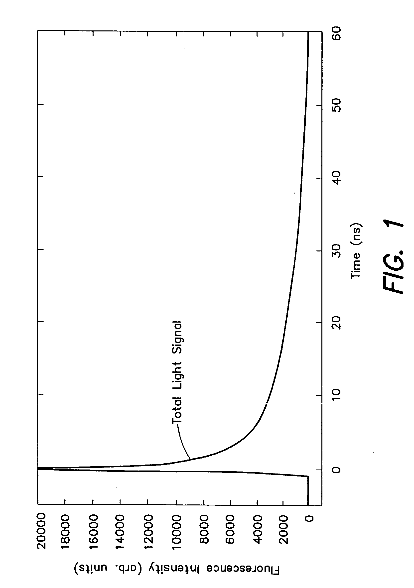
[0081] Prophetic data can be generated for several types of particles; non-fluorescent particles (scattered light only); particles containing a mixture of common atmospheric PAHs having representative lifetimes about 15, about 22, and about 30 ns; hazardous bioaerosols (respirable bioparticles) having a representative lifetime of about 2 ns; background bioaerosols (e.g., a pollen grain) having a typical lifetime of about 2 ns.

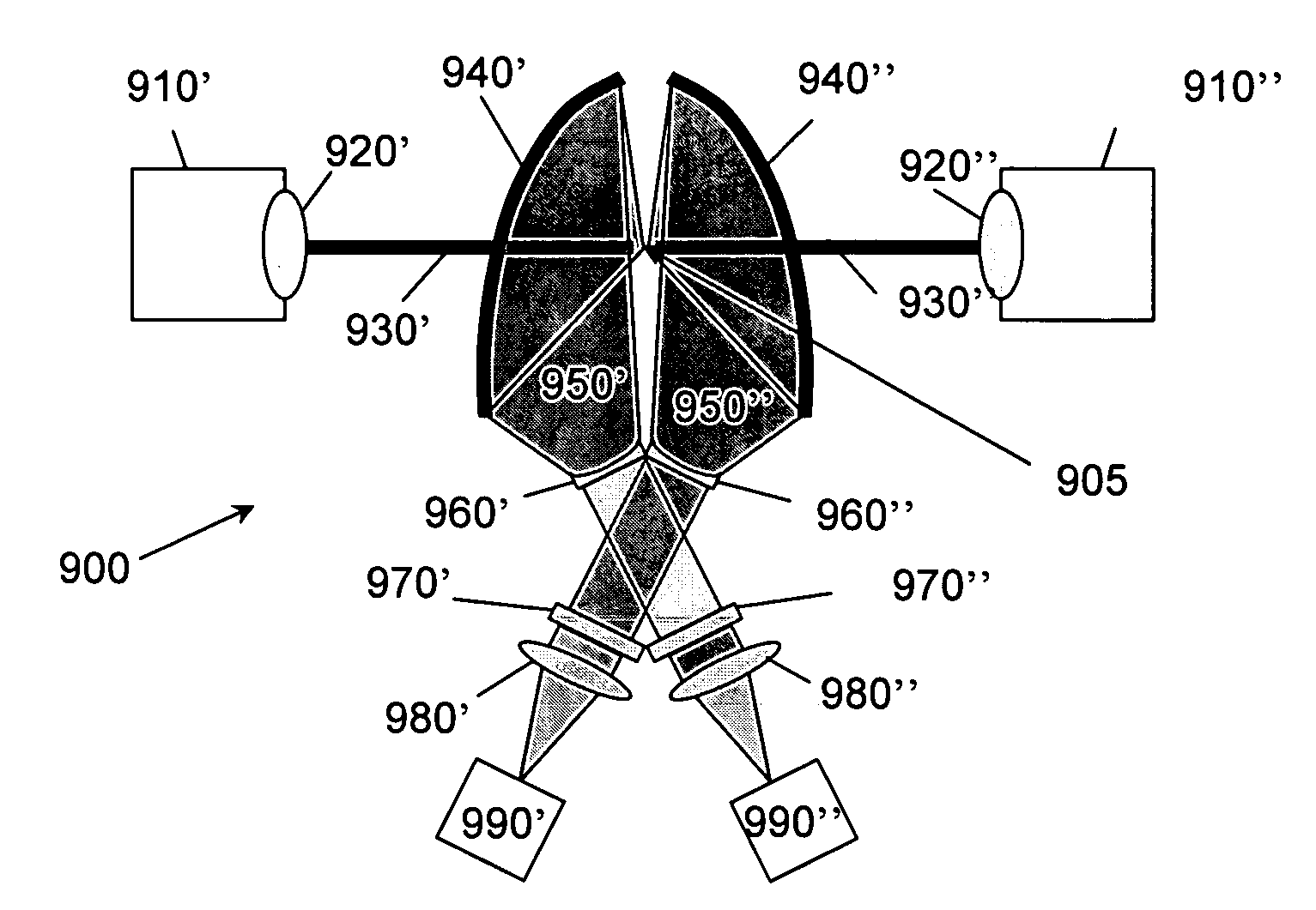
[0082] This prophetic example data is constructed to approximate the results expected from one example implementation of the present invention. The experimental system can comprise a quadrupled SURELITE I™ YAG laser emitting at 266 nm available from Continuum, Inc., and a flow cell comprising about two-inch cubic aluminum block bored through on three orthogonal axes. Aerosol particles are introduced isokinetically within an annular, particle-free sheath flow, wherein the aerosols interact with the emitted laser energy in a cen...

example 2

Analysis of a Prophetic Response

[0085] FLUOFIT™ software was used to analyze a convolved representative response to derive up to three exponential decay components and one scatter component. The resultant of this was a set of intensities and lifetimes that characterize different components of the decay. Intensities for short-lived fluorescence were summed and taken as representative of biofluorescence. Intensities for long-lived fluorescence were summed and taken as representative of PAH fluorescence. The IRF intensity was taken as representative of scattered light, which is typically related to particle size. The short- and long-lived fluorescence totals and scattered light total were used to locate the particle on a three-dimensional map to classify the various particles.

[0086] Table 1 lists exponential decay parameters of representative species that may be encountered. For PAHs, the “relative importance” (RI) is a measure of the importance with respect to fluorescence measureme...

example 3

Mapping Particle Characteristics

[0095] In this example, particle characteristics as represented by a discriminant vector were mapped according to their position in time-resolved fluorescence signal space.

[0096]FIG. 8 is a map showing the relative positions of each of the constructed particles analyzed in Example 2 with respect to a scatter component, a non-biological fluorescence component, and a biological fluorescence component. The discriminant vectors for each of the dust grain 1, PAH mixture 2, spore 3, pollen 4, and spore with PAH 5 were mapped.

[0097] As shown, the spatial groupings provided an indicating of the general composition of particle. Thus, the technique of mapping can be utilized to facilitate the characterization of the nature of particles based on the particle's deconvolved response. Other representative discriminant vectors have also been shown for comparison.

[0098] As discussed above, other mapping techniques can be utilized to characterize the nature of eac...


PUM


Abstract

The systems and methods of the invention utilize time-resolved techniques to deconvolve a measured response to characterize the nature of particles. The measured response is deconvolved into a scatter component and a fluorescence component. The fluorescence component is further characterized into biological and non-biological components. Probability techniques are utilized to predict whether the particles are biological or non-biological.

Description

CROSS-REFERENCE TO RELATED APPLICATIONS [0001] This application is a continuation-in-part of and claims the benefit under 35 U.S.C. §120 to pending U.S. patent application Ser. No. 10 / 797,716, entitled “System and Method for Bioaerosol Discrimination by Time-Resolved Fluorescence,” filed on Mar. 10, 2004, which claims priority under 35 U.S.C. §119(e) to U.S. Provisional Application Ser. No. 60 / 453,325, entitled “Method for Bioaerosol Discrimination by Time-Resolved Laser Induced Fluorescence (TRILIF),” filed on Mar. 10, 2003, each of which is herein incorporated by reference in its entirety.BACKGROUND OF THE INVENTION [0002] 1. Field of the Invention [0003] The invention relates to classifying particles and, in particular, to utilizing time-based fluorescence techniques to characterize the biological nature of aerosol particles. [0004] 2. Discussion of Related Art [0005] Detection of biological aerosol particles or bioaerosois can be important in many fields including, for example, ...

Claims


Application Information

Patent Timeline
IPC IPC(8): G01N21/64
CPCG01N15/1459G01N2001/2223G01N21/6408
Inventor BARNEY, WILLIAM S.DOERFLER, THOMAS E.
Owner TIAX LLC
Why Eureka
Try Eureka