Electronic circuit device
a technology of electronic circuit device and integrated circuit, which is applied in the direction of error detection/correction, instruments, general purpose stored program computers, etc., can solve the problems of long development time, performance encountering design complexity, and inability to respond quickly to market demands
- Summary
- Abstract
- Description
- Claims
- Application Information
AI Technical Summary
Benefits of technology
Problems solved by technology
Method used
Image
Examples
first embodiment
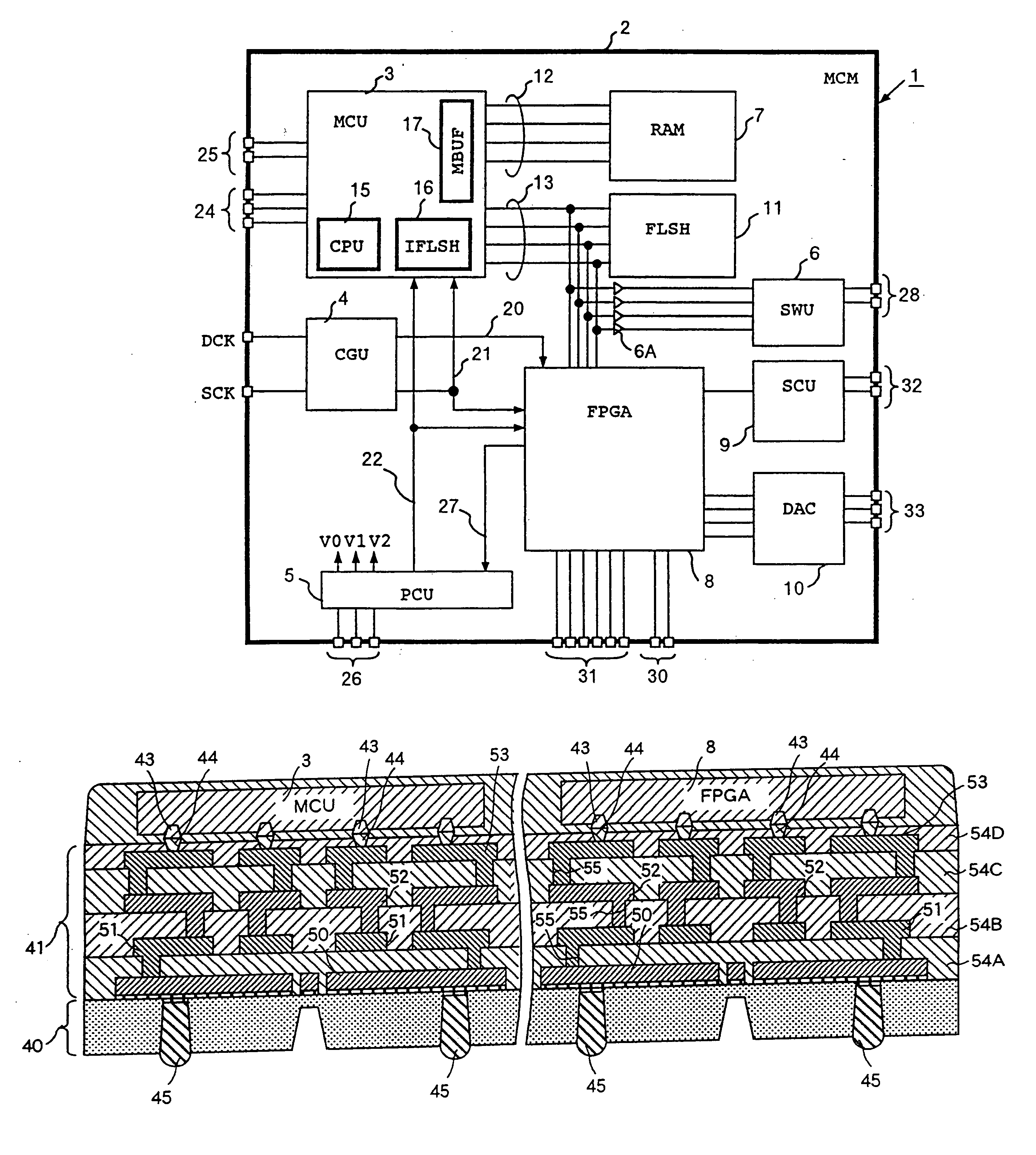
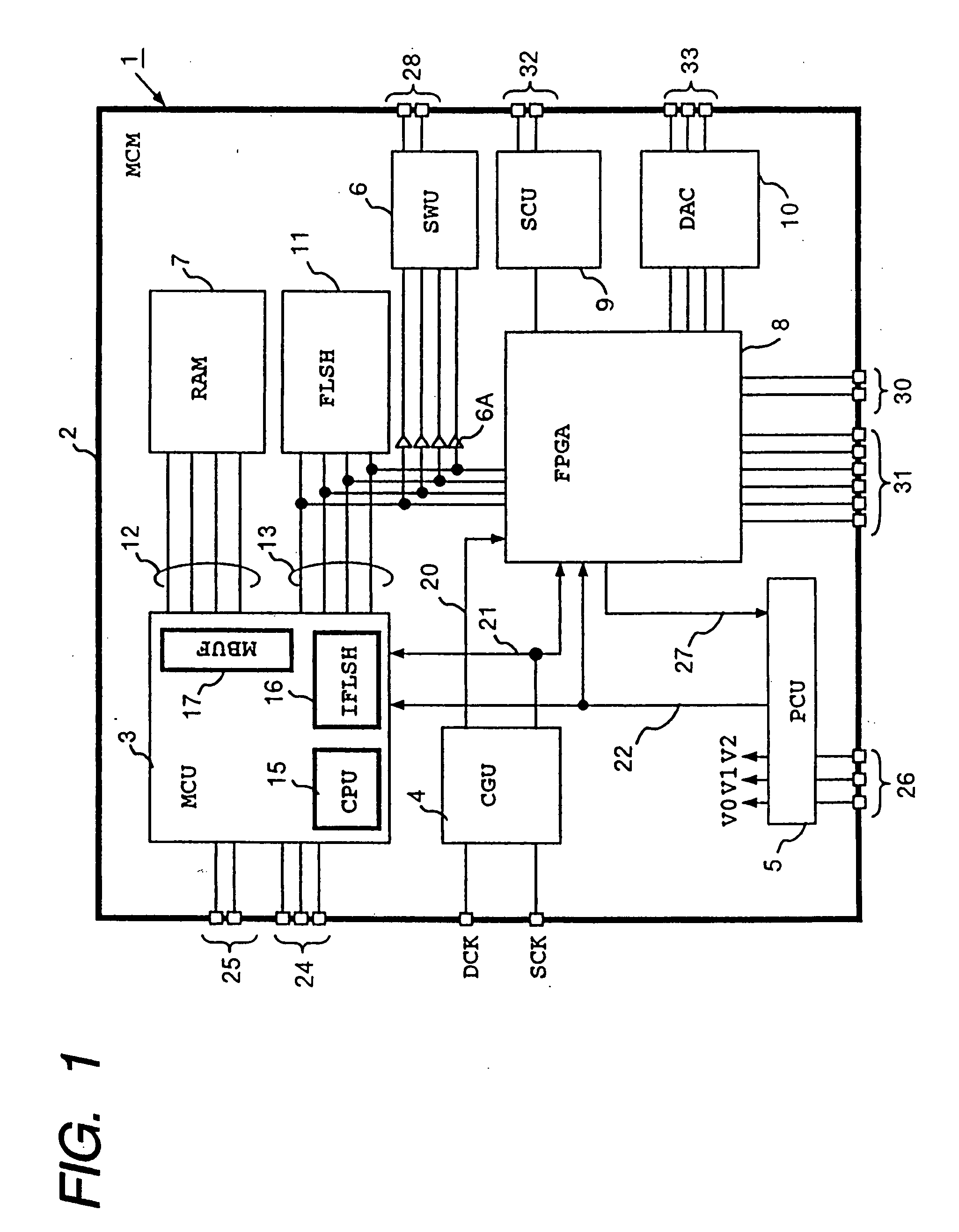
[0068]FIG. 1 shows an MCM 1 which is the inventive electronic circuit. This MCM 1 is intended in this example for the application to a system that is oriented to graphic control inclusive of display, imaging and data compression, although this affair is not compulsory.
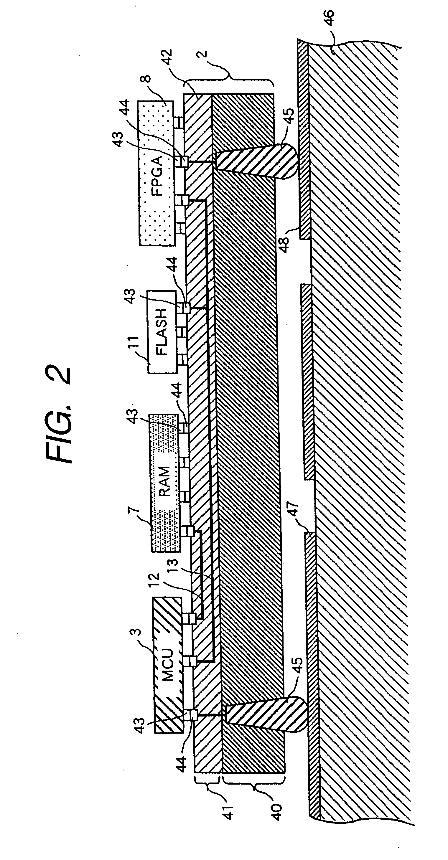
[0069] The MCM1 includes semiconductor devices formed on one side of a high-density mount board 2, which are a microcomputer (MCU) 3, clock generation unit (CGU) 4, power control unit (PCU) 5, switch unit (SWU) 6, random access memory (RAM) 7, programmable device (FPGA) 8, serial communication unit (SCU) 9, digital-to-analog converter (DAC) 10, and flash memory (FLSH) 11. The random access memory 7 is connected to the microcomputer 3 through an exclusive memory bus 12. The microcomputer 3, FPGA 8 and flash memory 11 share a common system bus 13.
[0070] The CGU 4 having inputs of a system clock signal SCK and display clock signal DCK multiplies or demultiplies the frequencies of these clock signals to release a resultin...
second embodiment
[0113]FIG. 6 shows an MCM 1A which is the inventive electronic circuit. This MCM 1A differs from the MCM 1 shown in FIG. 1 in the adoption of an MCU 3A which does not have the on-chip flash memory 16. The MCU is generally designed to incorporate the flash memory in case the high-speed operation of flash memory is intended or in case the confinement of high secrecy data within the LSI chip is intended. If these cases are not relevant, it is enough to use the MCU 3A without a flash memory.
[0114] Another elimination is the SWU 6 and PCU 5, and the operational power voltages V0, V1 and V2 are supplied directly from the outside. The program-end signal 27 is released from the mount board 2A to the outside, and the system reset signal 22 is given from the outside of the board 2A. The rest is the same as the preceding one shown in FIG. 1, and further explanation is omitted.
third embodiment
[0115]FIG. 7 shows an MCM 1B which is the inventive electronic circuit. This MCM 1B differs from the MCM 1 shown in FIG. 1 in the external connection of the flash memory 11 outside of the mount board 2B. The flash memory 11 and MCM 1B are mounted on the mother board 46. The flash memory is generally very slow in access speed relative to the memory bus, and therefore it can be outside of the mount board 2B unless otherwise required by the application system. Moreover, in case a significant difference in the storage capacity of the flash memory 11 depending on the application is anticipated, it is advantageous to have the flash memory 11 outside of the mount board 2 so as to gain the system flexibility.
[0116] Another elimination is the SWU 6 and PCU 5, and the operational power voltages V0, V1 and V2 are supplied directly from the outside. The program-end signal 27 is released from the mount board 2B to the outside, and the system reset signal 22 is given from the outside of the board...
PUM
 Abstract
Description
Claims
Application Information
 - R&D
- Intellectual Property
- Life Sciences
- Materials
- Tech Scout
- Unparalleled Data Quality
- Higher Quality Content
- 60% Fewer Hallucinations
Browse by: Latest US Patents, China's latest patents, Technical Efficacy Thesaurus, Application Domain, Technology Topic, Popular Technical Reports.
© 2025 PatSnap. All rights reserved.Legal|Privacy policy|Modern Slavery Act Transparency Statement|Sitemap|About US| Contact US: help@patsnap.com


