Method and apparatus for providing synchronization in a communication system

Active Publication Date: 2006-10-26
AVAGO TECH INT SALES PTE LTD
View PDF11 Cites 13 Cited by
  • Summary
  • Abstract
  • Description
  • Claims
  • Application Information

AI Technical Summary

Benefits of technology

[0007] The present invention is clock synchronization circuitry for a receiver in a communication system. In the first embodiment of the invention, the time stamp flags, which are generated from source clock in a known fixed period, are transmitted to the receiver. When the time stamp flags are detected at the receiver, the receiver translates the time stamp flags of a known fixed time interval into clock cycles that are compared to the sink local clock signal to generate an error value. The error value is processed in a loop filter and coupled to a first numerically controlled oscillator (NCO) to provide a coarse timing signal. The first NCO, a comparison circuit and loop filter forms a first loop. A second loop controls a second NCO to produce a finely controlled clock signal. In one embodiment of the invention, this circuit is used to maintain source-sink timing synchronization of a 27 MHz clock in a multimedia communications system such that frame drops are reduced.

Problems solved by technology

As such, any phase shift that occurs between the source and the sink circuitry due to channel dynamics causes a timing error to accumulate between the source and sink circuitry.

Method used


Image

  • Method and apparatus for providing synchronization in a communication system
  • Method and apparatus for providing synchronization in a communication system
  • Method and apparatus for providing synchronization in a communication system

Examples


first embodiment

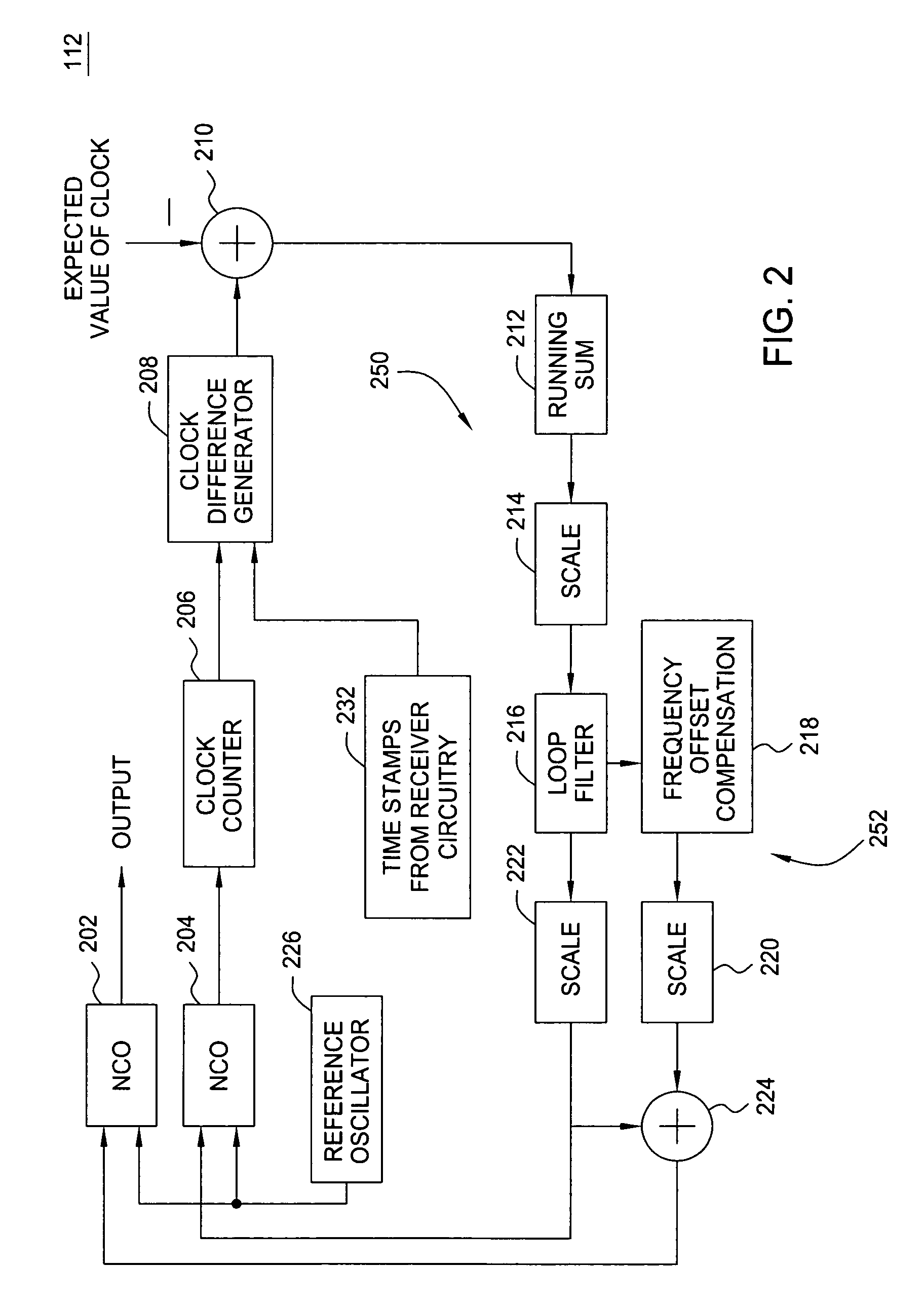
[0015]FIG. 2 depicts the sink clock circuit 112—a dual loop, digital phase lock loop (DPLL). The clock circuit 112 receives time stamps from the receiver circuit at block 232. The time stamps can be considered as a pulse generator that creates a pulse in a fixed time interval, for example, every 100 milliseconds based upon the use of a 27 MHz transmitter clock. The local 27 MHz clock for the receiver (output of circuit 112) is generated from the local reference oscillator 226, which, for example, is a 324 MHz oscillator. The reference oscillator 226 is coupled to the numerically controlled oscillator (NCO), 202 or 204. The NCOs take the clock signal of the reference oscillator 226 as an input and generate one cycle of the local 27 MHz clock for every 12 clock cycles of the 324 MHz oscillator, i.e., 324 MHz / 12=27 MHz. However, the local 27 MHz clock may have a slight frequency offset from the 27 MHz of the transmitter. Hence, the NCOs use the frequency offset information from a scale...

second embodiment

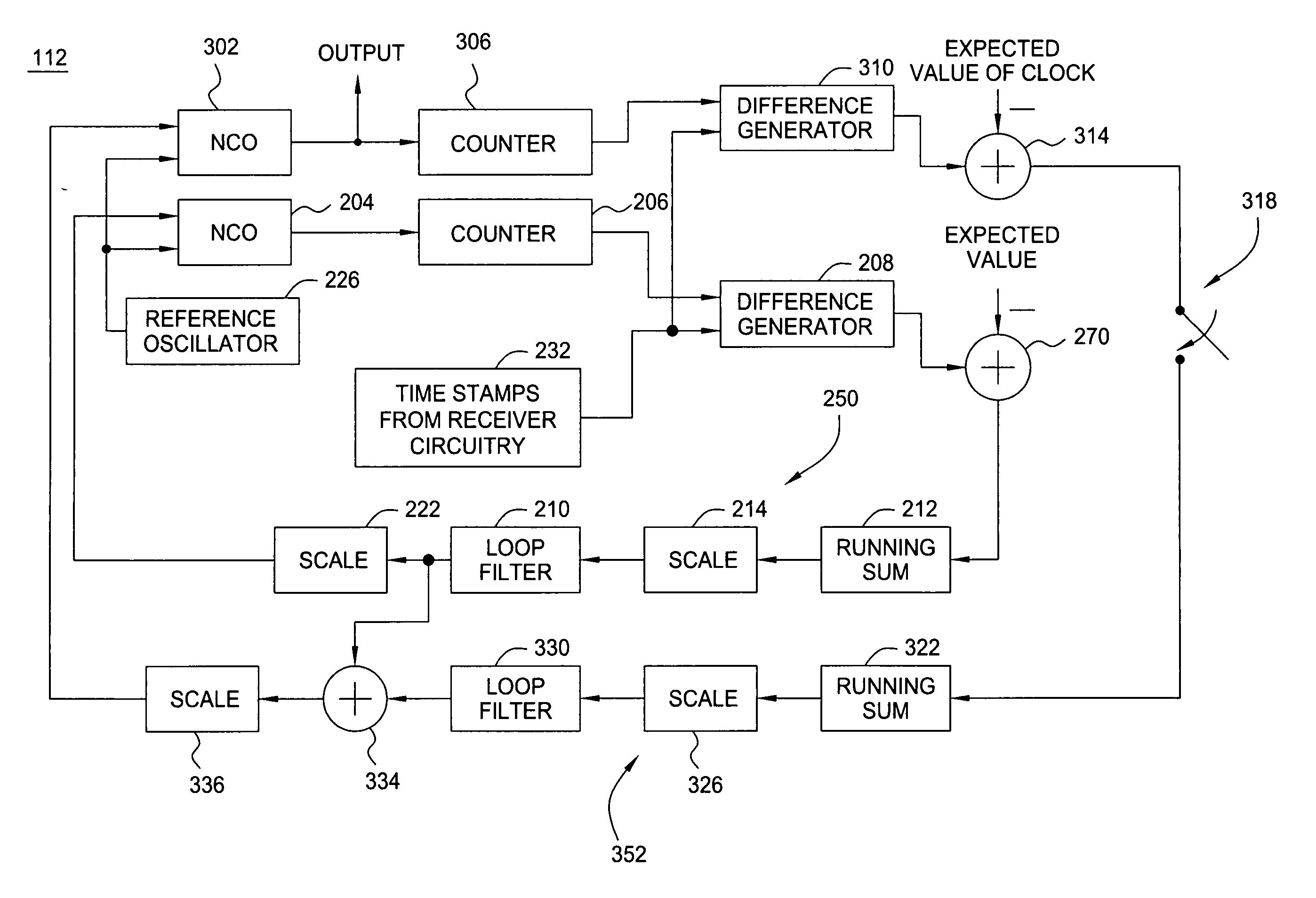
[0023]FIG. 3 depicts a block diagram of the sink clock circuit 112 of the present invention. The circuit 112 of FIG. 3 is similar to FIG. 2, except that a switched second loop 352 is used to adjust a corrected 27 MHz clock NCO 302. The common circuit elements have the same number and function as described with respect to FIG. 2. As such, the inner loop (first loop 250) comprising the difference generator 208, the subtractor 210, the running sum block 212, the scaler 214, the loop filter 216, the scaler 222, the NCO 204, and counter 206 all operate in the same manner as described above with respect to FIG. 2. These elements form the first loop 250 (an inner loop). The loop (outer loop 352) comprises difference generator 310, subtractor 314, switch 318, running sum block 322, scaler 326, loop filter 330, addition generator 334, scaler 336, NCO 302 and counter 306. This outer loop 352 is enabled by switch 318 after the inner loop 350 has reached a stable condition. The inner loop 350 i...


PUM


Abstract

A dual loop, clock synchronization circuit for a receiver in a communication system. The circuitry uses a first loop of a digital phase lock loop for coarse synchronization to time stamps within the received data and uses a second loop for fine synchronization of a second numerically controlled oscillator.

Description

BACKGROUND OF THE INVENTION [0001] 1. Field of the Invention [0002] The present invention relates to communication systems and, more particularly, to circuitry for providing accurate, synchronized timing between a transmitter and receiver of multimedia content. [0003] 2. Description of the Related Art [0004] Communication systems that communicate multimedia content, such as audio and video files, are required to utilize accurate timing such that the sequence of events within the multimedia content can be reconstructed at the receiver. To facilitate such timing synchronization certain protocols are applied to the transmission. The source circuitry (the transmitter) utilizes a time stamp flag (TSF) timer and a media access control (MAC) protocol such that a 27 MHz clock can be used in the source circuitry for timing of the transmission without directly encoding the clock into the transmission. [0005] The sink circuitry (the receiver) utilizes the TSF to properly order the multimedia i...

Claims


Application Information

Patent Timeline
IPC IPC(8): H03D3/24
CPCH03L7/07H03L7/087H04N21/4305H04N21/242H03L2207/50
Inventor LAI, YHEAN-SENMALKEMES, ROBERT CONRAD
Owner AVAGO TECH INT SALES PTE LTD
Why Eureka
Try Eureka