Ultrasonic imaging apparatus and ultrasonic imaging method

a technology of ultrasonic imaging and ultrasonic echoes, which is applied in the field of ultrasonic imaging apparatus and ultrasonic imaging method, can solve the problems of poor image visibility near the boundary, weak ultrasonic echoes from the interior of the bone part and the rear part of the bone part, and large ultrasonic echoes at the boundary

Inactive Publication Date: 2006-10-26
FUJIFILM HLDG CORP +1
View PDF3 Cites 44 Cited by
  • Summary
  • Abstract
  • Description
  • Claims
  • Application Information

AI Technical Summary

Benefits of technology

[0020] According to the present invention, the signal amplification factors of the group of reception signals are adjusted with respect to respective reception signals based on the mutual property of the group of reception signals representing ultrasonic echoes generated in a certain region, and therefore, signal components relating to certain tissue property contained in the group of reception signals can be extracted. Thereby, signals having small amplitude, which are often buried in signals having large amplitude, can be extracted. Accordingly, by performing phasing addition on the group of reception signals with thus adjusted signal amplification factors, a B-mode image clearly representing different tissues can be generated. That is, even in the case where a hard tissue exists nearby, a soft tissue can be clearly displayed in the image.

Problems solved by technology

However, in the case where there is a boundary having large reflectance in an ultrasonic wave transmission region, the intensity of ultrasonic echoes reflected at the boundary becomes extremely large.
On this account, the boundary in the ultrasonic image generated by STC is displayed with high brightness, and the visibility of the image near the boundary becomes poor.
On the other hand, since great reflection occurs in the bone part, ultrasonic echoes from the interior of the bone part and rear part of the bone part become very weak.
However, it is generally impossible to separate weak signal components representing information of the bone interior from the reception signals to which ringing has been added.
Further, regarding the ultrasonic echoes from the soft tissue present in front of the bone part, the visibility in the display screen is significantly deteriorated due to the presence of the ultrasonic echoes having large intensity generated on the surface of the bone part.
Thus, the ultrasonic echoes generated on the periphery of the hard tissue is buried in the ultrasonic echoes having large intensity generated in the hard tissue, and therefore, it is extremely difficult to clearly imaging the proximity to the hard tissue with high reflectance.
However, the art disclosed in JP-A-7-236637 is to improve the image quality of an entire ultrasonic image, but not to improve the image quality of the image representing the region near the tissue with high reflectance such as a bone part.
Thereby, an STC curve that does not extremely amplify the echo-free part, nor extremely reduce the gain for a part to be displayed specifically brighter than the periphery such as a tumor existing in a tissue and make it difficult to discriminate the part from the peripheral tissue.
However, the art disclosed in JP-A-7-323032 is also to improve the image quality of an entire ultrasonic image, but the improvement in the image quality of the image representing the region near the tissue with high reflectance cannot be expected.
However, in JP-A-11-235341, the correlation of reception signals between vibrators is obtained only for obtaining the similarity of the reception signals for evaluate the distortion of reception signals, but the tissue property within the object are not obtained or a specific tissue is not extracted based on the relationship between reception signals.
However, in the art disclosed in WO2001 / 80714, there is no viewpoint of extracting signals having small amplitude from signals having large amplitude, and therefore, an image representing the proximity to the hard tissue with high reflectance such as a bone part can not be displayed appropriately.

Method used


Image

  • Ultrasonic imaging apparatus and ultrasonic imaging method
  • Ultrasonic imaging apparatus and ultrasonic imaging method
  • Ultrasonic imaging apparatus and ultrasonic imaging method

Examples


first embodiment

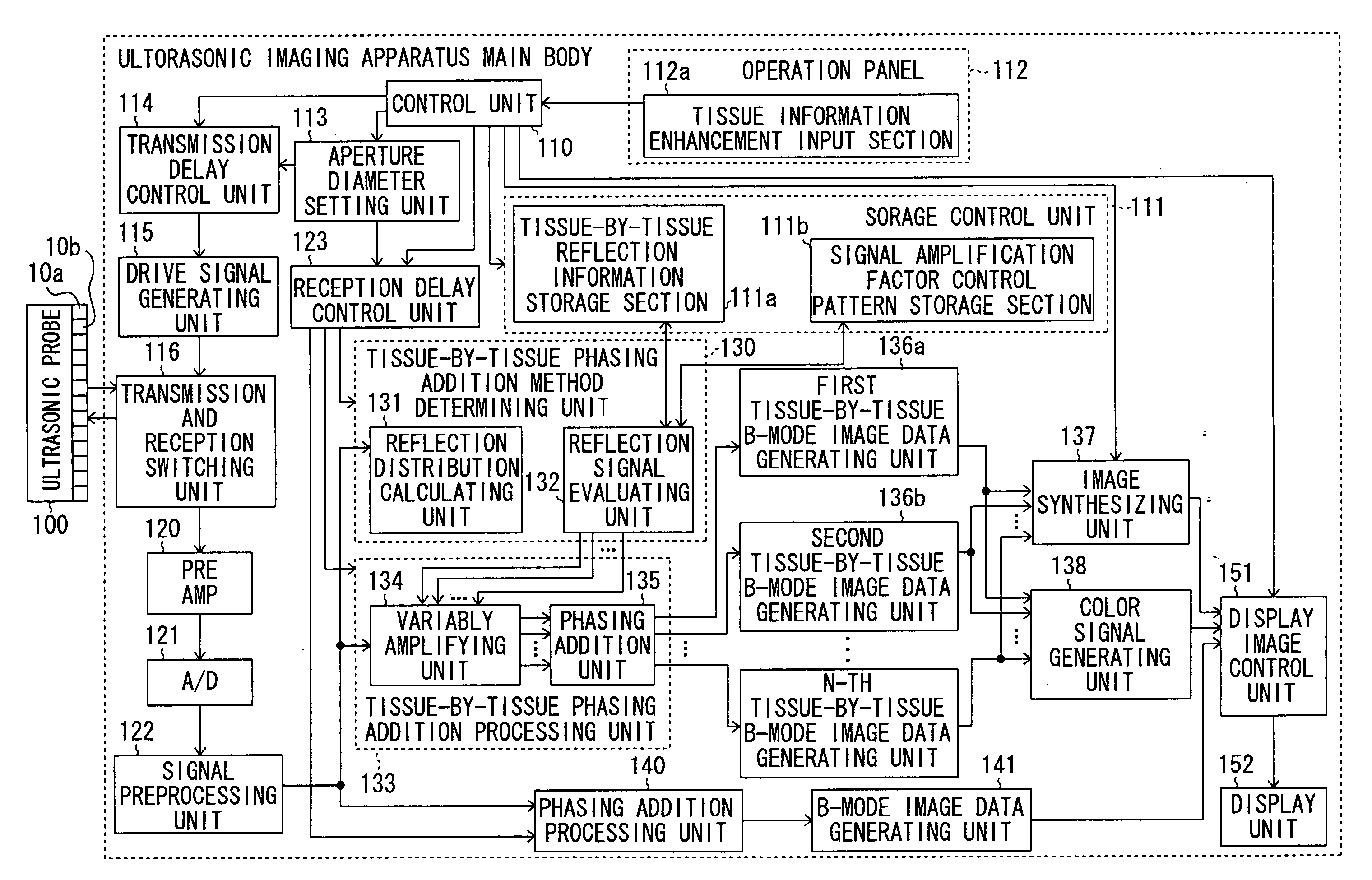
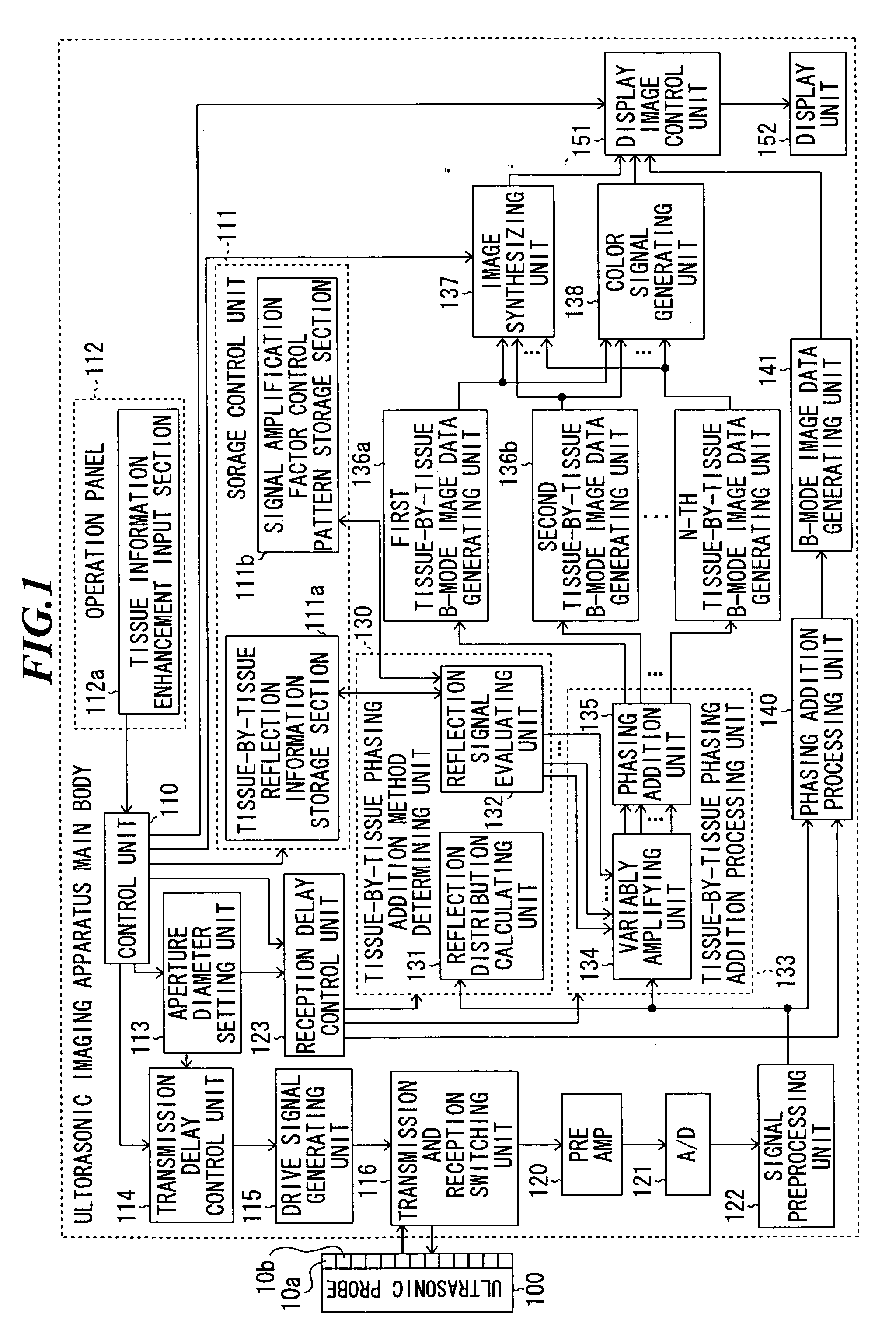
[0042]FIG. 1 is a block diagram showing a constitution of an ultrasonic imaging apparatus according to the present invention. The ultrasonic imaging apparatus according to the embodiment includes an ultrasonic imaging apparatus main body and an ultrasonic probe 100 connected to the ultrasonic imaging apparatus main body by a cable.

[0043] The ultrasonic probe 100 is used by being abutted on an object to be inspected to transmit an ultrasonic beam to the object and receive ultrasonic echoes propagating from the object. The ultrasonic probe 100 includes plural ultrasonic transducers 10a, 10b, . . . for transmitting ultrasonic waves based on applied drive signals and receiving ultrasonic echoes to output reception signals. These ultrasonic transducers 10a, 10b, . . . are arranged in a one-dimensional or two-dimensional manner to form a transducer array.

[0044] Each ultrasonic transducer is constituted by a vibrator in which electrodes are formed on both ends of a material having a piezo...

second embodiment

[0133] As a modified example of the ultrasonic imaging apparatus according to the present invention, various statistics values may be calculated based on the histogram corresponding to a reflection distribution of reception signals, and select an amplification factor control pattern to be applied to a group of reception signals. As the statistics values, mode, median, quartile deviation, skewness, frequency, etc. are used. Here, the quartile deviation is an indicator representing the degree of scattering of frequency, and the quartile deviation QR is obtained by the following expression using the first quartile X0.25 and the third quartile X0.75. The quartile is a value in a position where the frequency is divided into quarters when data is aligned in ascending order, and the first quartile is a value located at 25% in ascending order and the third quartile is a value located at 75% in ascending order.

QR=(X0.75−X0.25) / 2

[0134] Next, an ultrasonic imaging apparatus according to the t...

third embodiment

[0146] As described above, according to the present invention, the reflection distribution can be analyzed correctly with simple calculation by utilizing the beta distribution obtained based on the histogram corresponding to the reflection distribution of reception signals. Therefore, tissue-by-tissue B-mode images can be generated in real time.

[0147] In the third embodiment of the present invention, the amplification factor control pattern to be applied to the group of reception signals has been selected by analyzing the histogram using beta distribution, however, the amplification factor control pattern may be directly selected based on the parameters α and β of beta distribution.

[0148] The calculation processing means for performing calculation and evaluation of the reflection distribution that has been described in the above first to third embodiments can be added to a general ultrasonic imaging apparatus as an advanced feature. Therefore, a system for generating tissue-by-tiss...


PUM


Abstract

An ultrasonic imaging apparatus capable of displaying an ultrasonic image clearly representing different tissues by discriminating ultrasonic echoes generated in regions having different reflection characteristics among the received ultrasonic echoes. The ultrasonic imaging apparatus includes: an ultrasonic probe including plural ultrasonic transducers for transmitting ultrasonic waves toward an object to be inspected and receiving ultrasonic echoes propagating from the object to output reception signals; a reflection signal evaluating unit for evaluating mutual property of a group of reception signals relating to a region within the object from among the reception signals respectively outputted from the plural ultrasonic transducers; and a variable amplifying unit for amplifying the group of reception signals with signal amplification factors determined with respect to respective reception signals based on an evaluation result of the reflection signal evaluating unit.

Description

BACKGROUND OF THE INVENTION [0001] 1. Field of the Invention [0002] The present invention relates to an ultrasonic imaging apparatus and an ultrasonic imaging method for performing imaging of organs, bones, etc. within a living body by transmitting and receiving ultrasonic waves so as to generate ultrasonic images to be used for medical diagnosis. [0003] 2. Description of a Related Art [0004] In an ultrasonic imaging apparatus to be used for medical diagnoses, an ultrasonic probe including plural ultrasonic transducers having transmitting and receiving functions of ultrasonic waves is used. When an ultrasonic beam formed by synthesizing plural ultrasonic waves is transmitted from such an ultrasonic probe to an object to be inspected, the ultrasonic beam is reflected at a boundary between regions having different acoustic impedances, i.e., between tissues within the object. Thus generated ultrasonic echoes are received and an image is constructed based on the intensity of the ultraso...

Claims


Application Information

Patent Timeline
Patent Type & Authority Applications(United States)
IPC IPC(8): A61B8/00
CPCA61B8/463A61B8/14
Inventor KARASAWA, HIROYUKI
Owner FUJIFILM HLDG CORP
Why Eureka
Try Eureka