Ultrasonic probe

Inactive Publication Date: 2006-10-26
FUJIFILM HLDG CORP +2
View PDF8 Cites 7 Cited by
  • Summary
  • Abstract
  • Description
  • Claims
  • Application Information

AI Technical Summary

Benefits of technology

[0007] A main object of the present invention is to provide an ultrasonic probe which has improved receiver sensitivity with using a general material for a cap.
[0015] In this case, it is preferable that the cap has a cylindrical shape and the density interval is gradually changed in an axial direction and / or a circumference direction of the cap. In addition, it is preferable that the density interval is gradually changed from a center toward ends in the axial direction of the cap such that the acoustic impedance gradually becomes higher from the center toward the ends, so as to give an acoustic lens effect to the cap in the axial direction.
[0016] According to the present invention, since the cap includes the high- and low-density area where the low material density parts and high material density parts are alternately formed for transmitting the ultrasonic waves, and the density interval of the high- and low-density area is smaller than the wavelength of the ultrasonic wave, the high- and low-density area is deemed to have a uniform acoustic impedance to the ultrasonic waves, reducing the acoustic impedance of the cap. Accordingly, a consistency of the acoustic impedances between the cap and the living organism is improved so that a receiver sensitivity of the ultrasonic transducer is increased. In addition, such cap can be easily formed of a conventional resin material with low cost.

Problems solved by technology

However, the resin has high acoustic impedance which cannot match that of the living organism, which lowers receiver sensitivity of the ultrasonic transducer.
However, to use a new resin material as an alteration of known current resin material, an enormous cost and work is needed to research and test the new material so as to confirm biocompatibility thereof.
Accordingly, the use of new material is not practical.

Method used


Image

  • Ultrasonic probe
  • Ultrasonic probe
  • Ultrasonic probe

Examples


Embodiment Construction

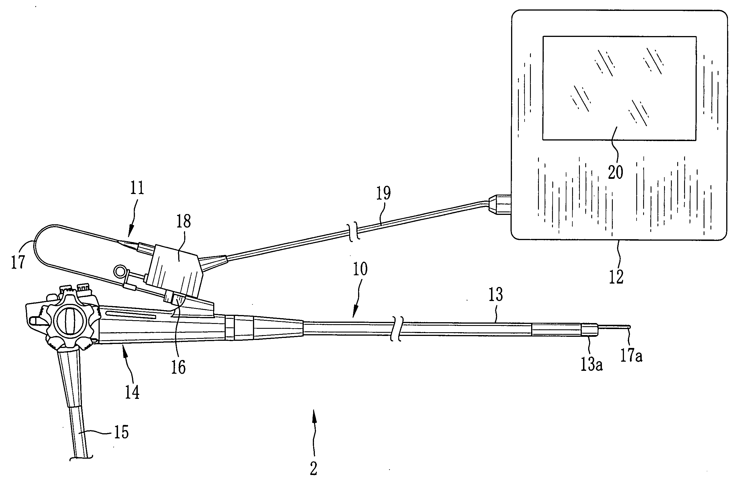
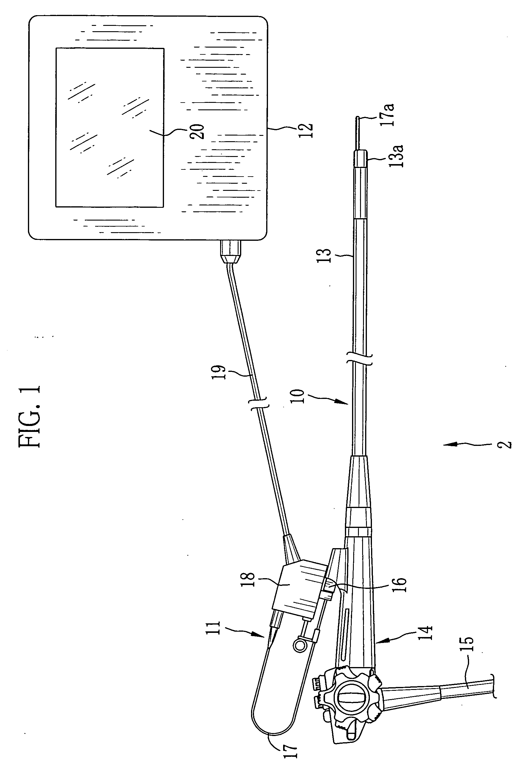
[0029] As shown in FIG. 1, an ultrasonic diagnosing system 2 is composed of an endoscope 10, ultrasonic probe 11 and an ultrasonic observer 12. The endoscope 10 comprises a flexible insertion section 13 for being inserted into a living organism, an operation section 14 connected to a tail end of the insertion section 13, and a cord 15 connecting between the operation section 14 and a processor for endoscope (not shown). At a leading end 13a of the insertion section 13, a camera (not shown) for capturing images of inside the living organism is incorporated. The image captured by the camera is displayed on a monitor for endoscope (not shown) through the processor for endoscope.

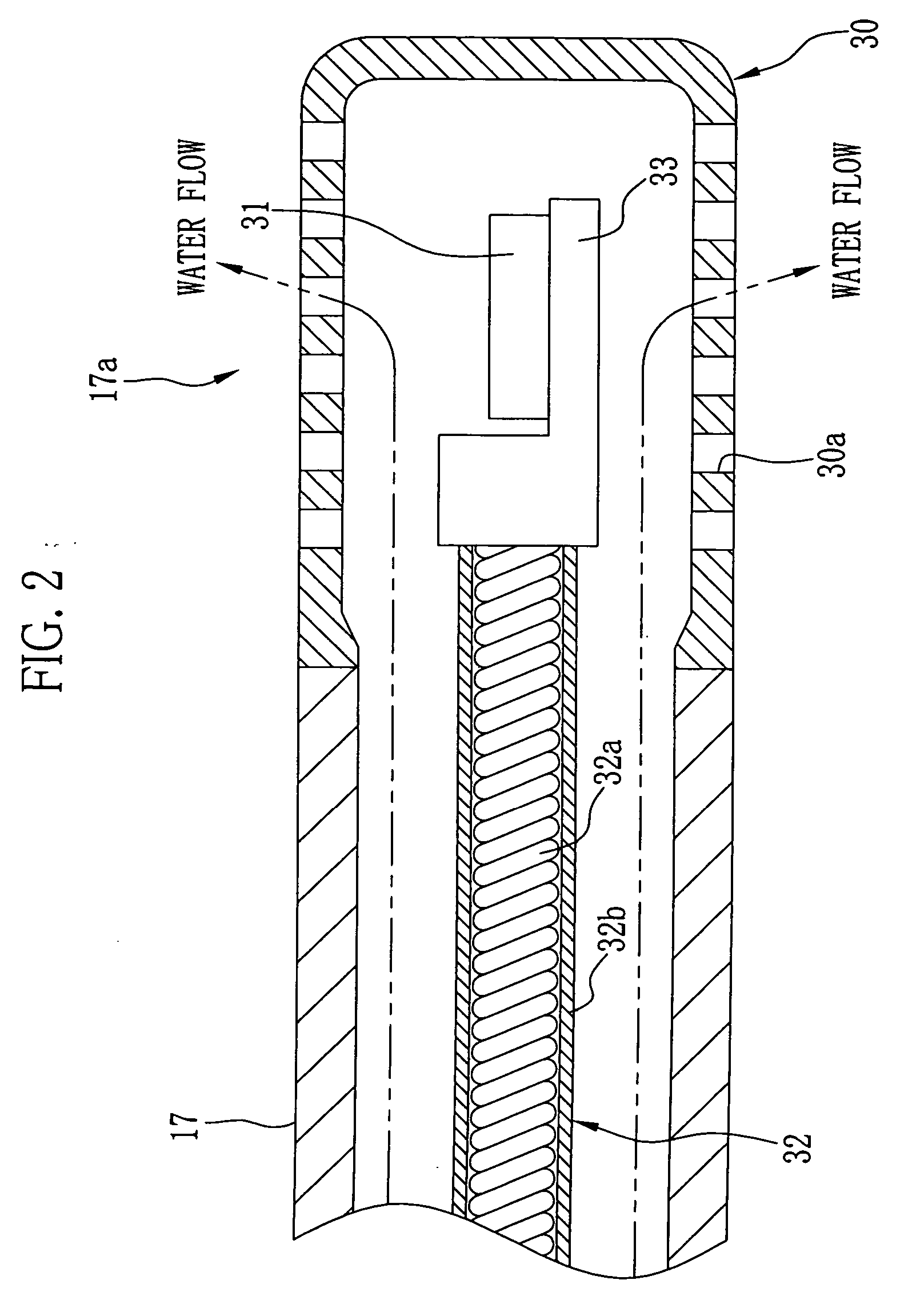
[0030] The ultrasonic probe 11 is composed of a flexible sheath 17 for penetrating the insertion section 13 from a forceps inlet 16 of the endoscope 10, a translator 18 incorporating a motor 49 and other members (refer to FIG. 3) described later, and a cord 19 connecting between the translator 18 and the ultras...


PUM


Abstract

The ultrasonic probe has an ultrasonic transducer for sending and receiving ultrasonic waves, and a cap covering the ultrasonic transducer. The ultrasonic transducer scans a living organism with the ultrasonic waves passing through the cap. A meshed area having plural holes is provided in a portion of the cap for transmitting the ultrasonic waves. By reducing a density interval (pitch of the holes) below a wavelength of the ultrasonic wave, an acoustic impedance of the meshed area is reduced. Water flows into the cap from a sheath, and then flows outside the cap through the holes. A concave can be alternative to the hole. In addition, the pitch of the holes or concaves may be uneven in the meshed area, so as to give an acoustic lens effect to the cap.

Description

BACKGROUND OF THE INVENTION [0001] 1. Field of the Invention [0002] The present invention relates to an ultrasonic probe which scans inside a living organism by ultrasonic, with use of an ultrasonic transducer. [0003] 2. Description Related to the Prior Art [0004] Recently, in a field of medical care, a medical diagnosis using ultrasonic images is widely used. The ultrasonic image is obtained by emitting ultrasonic waves to a required area of a living organism from an ultrasonic probe, and electrically detecting echo signal reflected from the living organism. In addition, when the ultrasonic waves scan the living organism, an ultrasonic tomography can be obtained. For this purpose, it is known an ultrasonic probe having a scanning mechanism for mechanically rotating, swinging or sliding an ultrasonic transducer which transmits / receives the ultrasonic waves. To obtain an ultrasonic image of inside the living organism with use of such ultrasonic probes, an operator inserts the ultraso...

Claims


Application Information

Patent Timeline
IPC IPC(8): A61B8/14A61F2/958
CPCA61B8/12A61B8/4461A61B8/445
Inventor OSAWA, ATSUSHITANAKA, TOSHIZUMIITOI, HIROMU
Owner FUJIFILM HLDG CORP
Why Eureka
Try Eureka