Revolver for firing high velocity ammunition

a high-speed, ammunition technology, applied in the field of revolvers, can solve the problems of concomitant loss of pressure and bullet velocity, increased production costs, and increased production costs, so as to reduce the amount of erosion, prolong the barrel life of the handgun, and smooth the translation

Active Publication Date: 2006-11-02
SMITH & WESSON
View PDF24 Cites 17 Cited by
  • Summary
  • Abstract
  • Description
  • Claims
  • Application Information

AI Technical Summary

Benefits of technology

[0008] One advantage of the revolver of the present invention is that a space between a rearward portion of the barrel and a forward surface of the cylinder can be adjusted longitudinally within a shroud housing the barrel from a forward end of the barrel. Such adjustment is typically effected by the use of one or more spacers. By allowing the position of the barrel to be adjusted in such a manner, the need to broach the rearward surfaces of the barrel is eliminated.
[0009] Another advantage is that the barrel is provided with a forcing cone integrally formed at the rearward opening thereof. The forcing cone (and/or the rear surface of the barrel) can be polished or otherwise finished to provide a reflective surface that reduces the amount of erosion that can result from using the revolver with high velocity ammunition. Thus, because the surface of the cone is subject to less erosion, the barrel life of the handgun can be extended. Furthermore, the geometry of the surface of the cone in conjunction with the reflective finish allows the projectile of the high velocity ammunition to show a smoother translation across the BC gap, thereby showing improved performance results in the revolver....

Problems solved by technology

Handguns, however, have not been capable of muzzle velocities of this magnitude, and have an upper bound of about 1,500 fps.
In such revolvers, the hot gases generated by the ignition of the powder are vented out the cylinder and down the barrel, with some venting at the BC gap, with a concomitant loss of pressure and bullet velocity.
This broaching method produces tool marks on the end surface of the barrel adjacent the cylinder and oftentime...

Method used


Image

  • Revolver for firing high velocity ammunition
  • Revolver for firing high velocity ammunition
  • Revolver for firing high velocity ammunition

Examples


Embodiment Construction

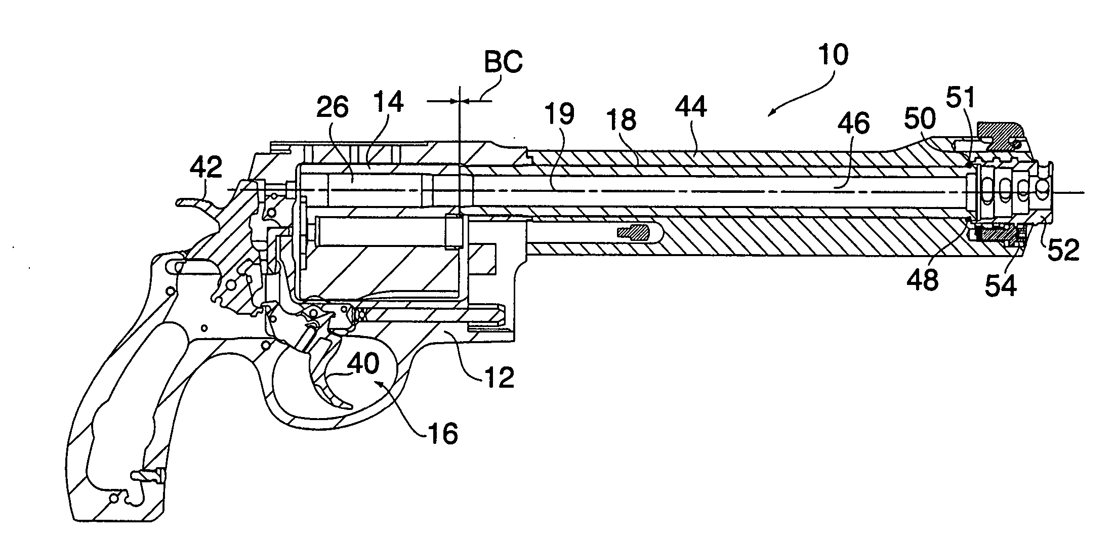
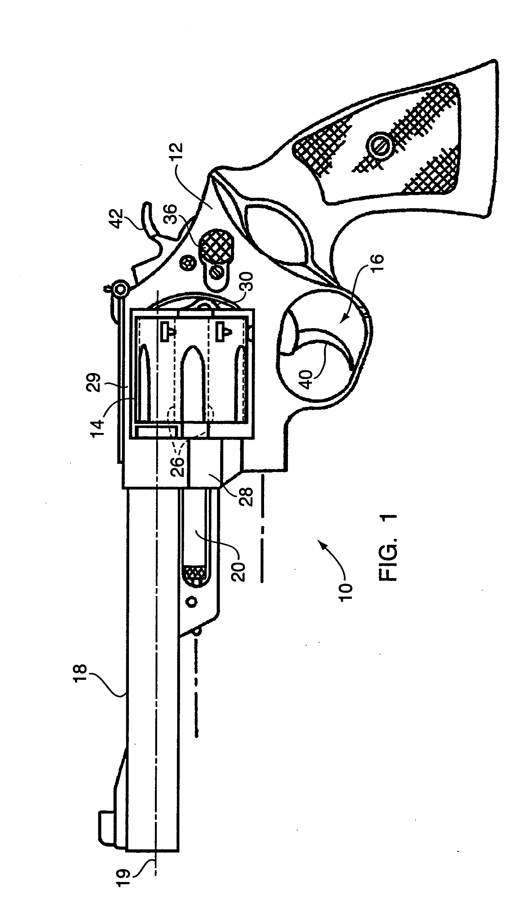
[0027] Referring to FIG. 1, one exemplary embodiment of a firearm incorporating the present invention is shown generally at 10 and is hereinafter referred to as “firearm 10.” The firearm 10 is preferably a revolver (as described in U.S. Pat. Nos. 6,330,761 and 6,523,294, which are incorporated herein by reference) that includes a frame 12, a cylinder 14, a firing mechanism 16, and a barrel 18. A firing axis 19 extends coaxially with the barrel 18. High velocity ammunition is the preferred type of ammunition for use in the firearm 10, such ammunition typically being capable of attaining bullet muzzle velocities of about 2,500 feet per second or greater.

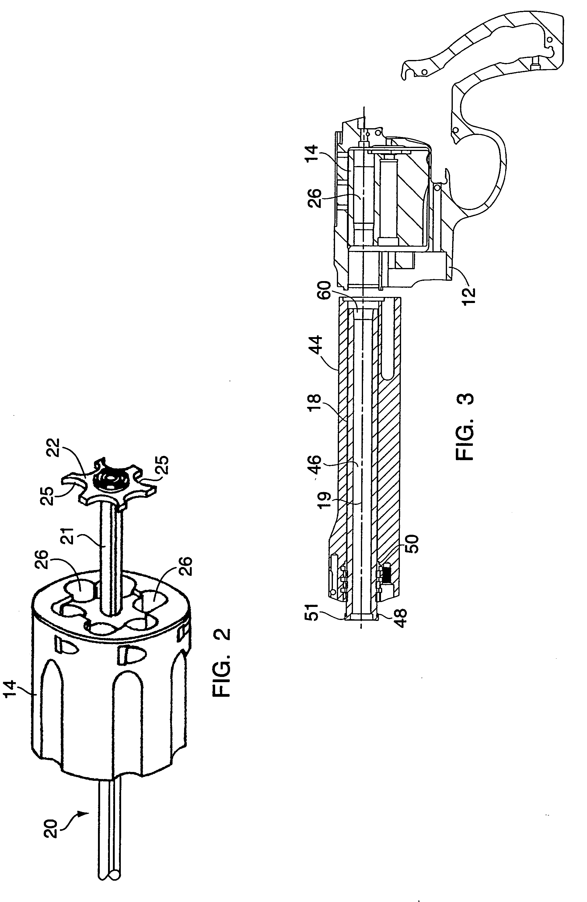
[0028] The cylinder 14 is pivotally mounted in the frame 12 and includes an ejector 20, a ratchet 22, and a plurality of chambers, two of which are shown at 26. The chambers 26 are configured to receive and align cartridges with the barrel 18. The cylinder 14 is pivotally mounted on a yoke 28 that is attached to the frame 12. A top st...


PUM


Abstract

A revolver for firing high velocity ammunition includes a frame, a cylinder, a barrel, and a firing mechanism. The revolver may include one or more of the following, each of which is especially adapted for use in the context of firing high velocity ammunition: spacers for adjusting a barrel-cylinder gap, for eliminating broaching of the rearward surface(s) of the barrel; a forcing cone formed in the rearward opening of the barrel for accommodating deformed projectiles; a reflective surface (e.g., mirrored surface) provided on the cone and/or barrel rearward surfaces, for reducing erosion resulting from using high velocity ammunition; gain-twist rifling in the barrel for a smoother transition to full projectile velocity; a larger diameter, hardened firing pin bushing for minimizing brass flow in the rearward direction; and a front sight assembly that minimizes lateral shift or drift of the sight pin during firing.

Description

[0001] This application claims the benefit of U.S. Provisional Application Ser. No. 60 / 627,491 filed Nov. 12, 2004, hereby incorporated by reference in its entirety.TECHNICAL FIELD [0002] The present invention relates generally to firearms and, more particularly, to revolvers having modified structures that are adapted for the firing of high velocity ammunition. BACKGROUND [0003] High velocity ammunition is well known for use in rifles and other long guns. Ammunition of this type is characterized by muzzle velocities in excess of 2,500 feet per second (fps). Handguns, however, have not been capable of muzzle velocities of this magnitude, and have an upper bound of about 1,500 fps. Revolvers present the added challenge of a barrel-cylinder (BC) gap to allow for cylinder rotation. In such revolvers, the hot gases generated by the ignition of the powder are vented out the cylinder and down the barrel, with some venting at the BC gap, with a concomitant loss of pressure and bullet veloc...

Claims


Application Information

Patent Timeline
IPC IPC(8): F41C3/14
CPCF41A3/74F41A3/76F41G1/02F41A21/36F41C3/14F41A21/18
Inventor DUBOIS, JASON ROBERTMUSKA, SIMON MICHAELZUKOWSKI, GARY E.AVEDISIAN, JOHN W.CURRY, BRETT
Owner SMITH & WESSON
Why Eureka
Try Eureka