Gasifier injector

Active Publication Date: 2006-11-02
GAS TECH INST +1
View PDF47 Cites 74 Cited by
  • Summary
  • Abstract
  • Description
  • Claims
  • Application Information

AI Technical Summary

Benefits of technology

[0009] The resulting gasification reaction generates extremely high temperatures and abrasive matter, e.g. slag, at or near the injector face plate. However, the coolant system incorporated within th

Problems solved by technology

The resulting gasification reaction generates extremely high temperatu

Method used


Image

  • Gasifier injector
  • Gasifier injector
  • Gasifier injector

Examples


Embodiment Construction

[0021] The following description of the preferred embodiments is merely exemplary in nature and is in no way intended to limit the invention, its application or uses. Additionally, the advantages provided by the preferred embodiments, as described below, are exemplary in nature and not all preferred embodiments provide the same advantages or the same degree of advantages.

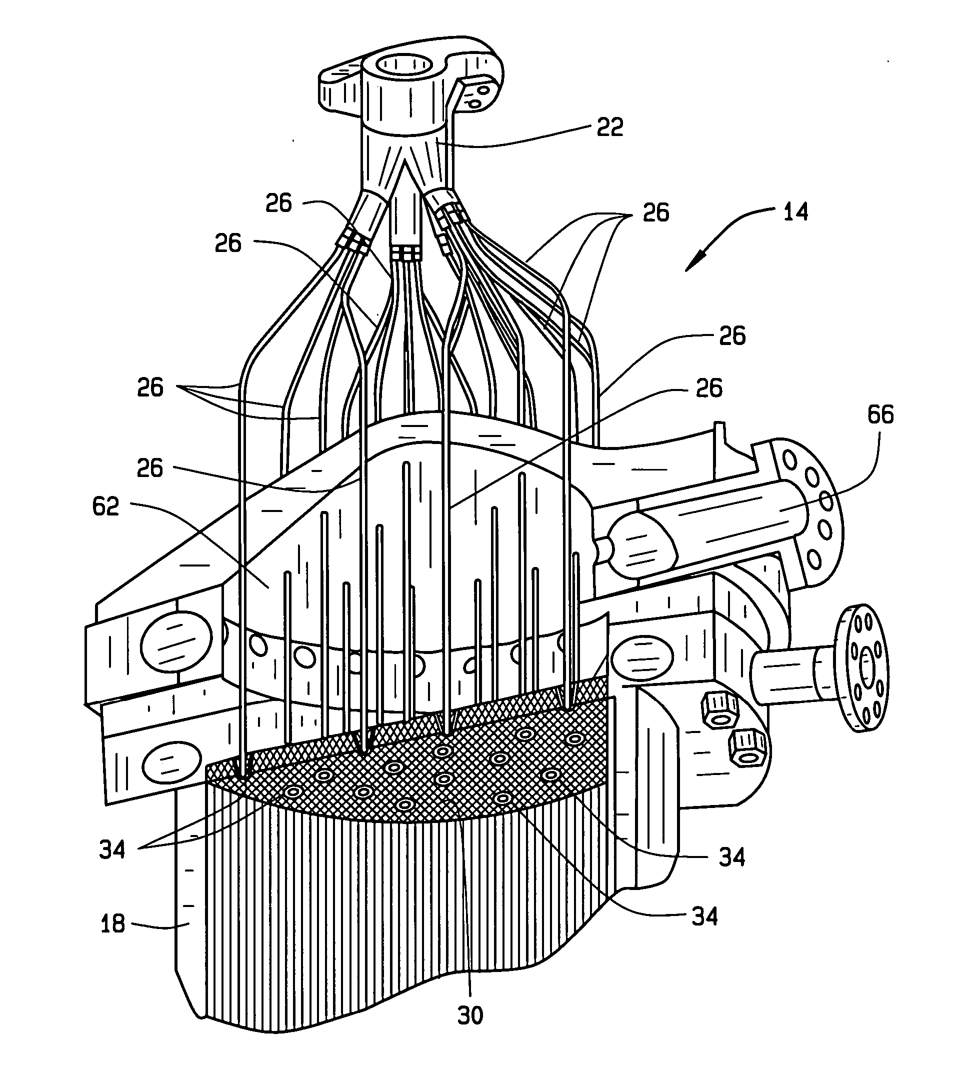
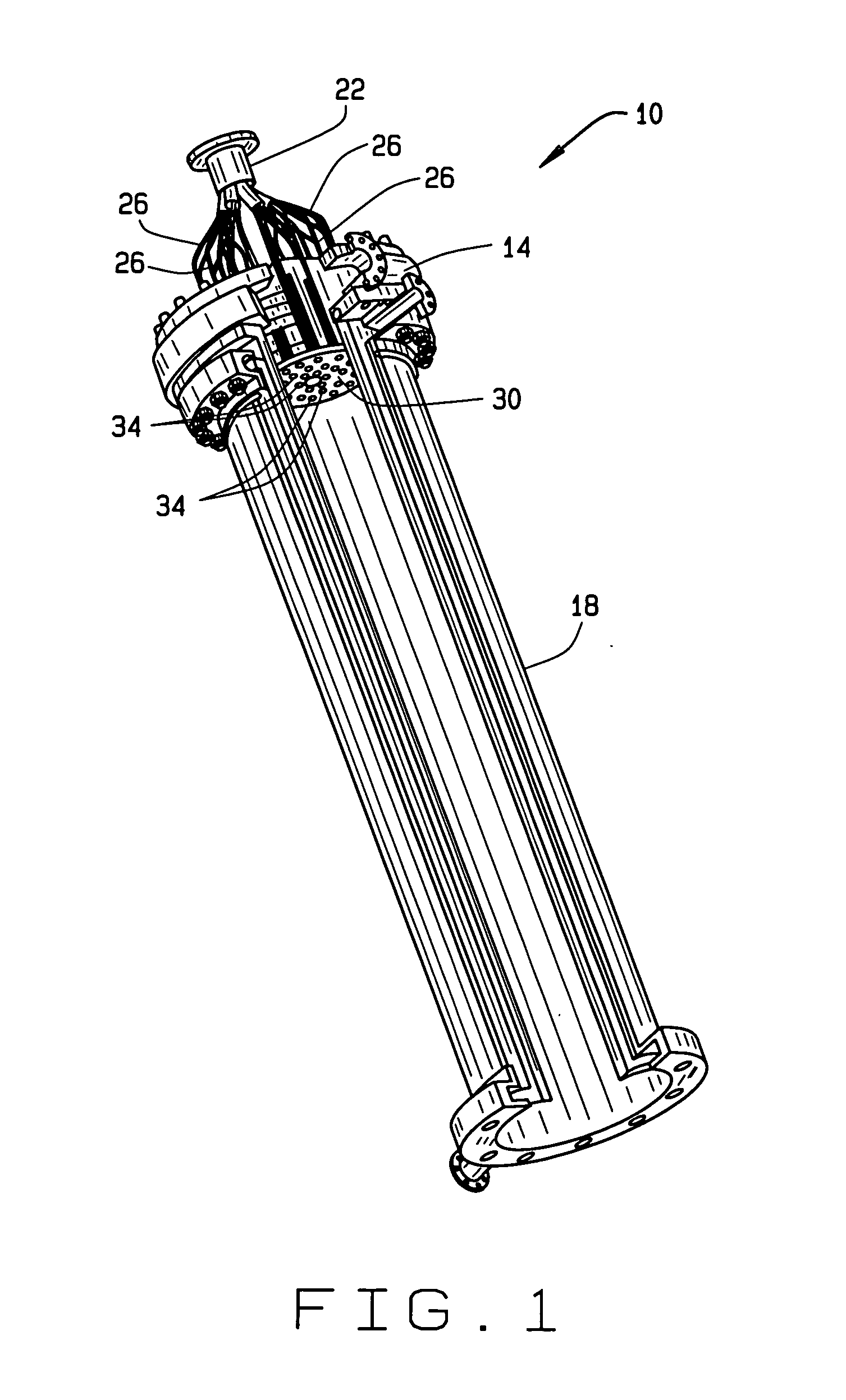
[0022]FIG. 1 illustrates a gasifier system 10 including an injector module 14 coupled to a gasification chamber 18. The injector module 14 is adapted to inject a high pressure slurry stream into the gasification chamber 18 and impinge a high pressure reactant onto the high pressure slurry stream to generate a gasification reaction within the gasification chamber 18 that converts the slurry into a synthesis gas. More specifically, the injector module 14 mixes a carbonaceous material, such as coal or petcoke, with a slurry medium, such as nitrogen N2, carbon dioxide CO2 or a synthesis gas, for example, a mixture of h...


PUM


Abstract

A gasifier injection module includes a two-stage slurry splitter and an injector face plate with a coolant system incorporated therein. The two-stage slurry splitter includes a main cavity into which a main slurry flow is provided. The main cavity includes a plurality of first stage flow dividers that divide the main slurry flow into a plurality of secondary slurry flows that flow into a plurality of secondary cavities that extend from the main cavity. Each secondary cavity includes a plurality of second stage flow dividers that divide each secondary slurry flow into a plurality of tertiary slurry flows that flow into a plurality of slurry injection tubes extending from the secondary cavities. The tertiary flows are injected as high pressure slurry streams into the gasification chamber via the slurry injection tubes. A reactant is impinged at high pressure, as an annular shaped spray, on each high pressure slurry stream via a plurality of annular impinging orifices incorporated into the injector face plate. The coolant system incorporated within the injector face plate maintains the injector face plate at a temperature sufficient to substantially reduce or prevent damage to the injector face plate by high temperatures and/or abrasive matter created by the resulting gasification reaction.

Description

CROSS-REFERENCE TO RELATED APPLICATIONS [0001] The present application is related in general subject matter to U.S. Patent Application Publication No. 2004 / 0071618, titled Method and Apparatus For Continuously Feeding And Pressurizing A Solid Material Into A High Pressure System, filed Oct. 15, 2003, assigned to The Boeing Co., and hereby incorporated by reference into the present application. The subject matter of the present application is also related to U.S. patent application Ser. No. 10 / 677,817, titled Regeneratively Cooled Synthesis Gas Generator, filed Oct. 2, 2003, presently allowed, the disclosure of which is also hereby incorporated by reference. Additionally, the subject matter of the present invention is related to U.S. patent application Ser. No. 11 / 081,144, titled Compact High Efficiency Gasifier, filed Mar. 16, 2005. Finally, the subject matter of the present application is related to U.S. Patent titled High Pressure Dry Coal Slurry Extrusion Pump, Attorney Docket No...

Claims


Application Information

Patent Timeline
IPC IPC(8): C10J3/00
CPCB05B7/066C10J2200/152C10J3/50B05B7/0861
Inventor SPROUSE, KENNETH M.FARHANGI, SHAHRAMMATTHEWS, DAVID R.
Owner GAS TECH INST
Why Eureka
Try Eureka