Refractory block and refractory wall assembly

a technology of refractory blocks and refractory walls, applied in the field of refractory arts, can solve the problems of eroding the strength of metallic panels, buckling and distortion, deterioration and failure of metallic panels, etc., and achieves the effects of improving wall structure, reducing heat transfer, and being easy to assembl

Inactive Publication Date: 2006-11-02
HARBISON WALKER REFRACTORIES
View PDF41 Cites 43 Cited by
  • Summary
  • Abstract
  • Description
  • Claims
  • Application Information

AI Technical Summary

Benefits of technology

[0011] An advantage of the present invention is an improved wall structure for a clinker cooler.
[0012] Another advantage of the present invention is a wall structure as defined above that is easier to assemble than wall structures known heretofore.
[0013] Another advantage of the present invention is a wall structure as defined above that can accommodate for variations or waviness in the outer, metallic shell of the cooler structure.
[0014] A still further advantage of the present invention is a wall structure as defined above that reduces heat transfer from the cooler blocks to the metallic panel.
[0015] A still further advantage of the present invention is a wall structure as defined above that does not require threaded fasteners to attach the cooler block to the metallic panel of the cooler structure.
[0016] Another advantage of the present invention is a wall structure as defined above that is formed of interlocking cooler blocks.

Problems solved by technology

A problem with cooler blocks of the type heretofore described is that the metal clip that is embedded within the block, and the metallic rod that is connected thereto, act as heat sinks.
At times, the heat in the metal rod can cause its deterioration and failure over time.
In addition, the metal rod conducts heat to the metallic panel of the cooler structure thereby eroding the strength of the metallic panel and causing buckling and distortion.
Another problem with the foregoing design is that it requires that holes be drilled into the metallic panel of the cooler structure, which reduces the overall structural integrity of the metallic panel.
This together with the aforementioned heating of the panel can cause the buckling and distortion of the shell panel.
Another problem associated with cooler blocks known heretofore is the assembly and disassembly of such structure.
As will be appreciated, aligning the metallic rod with the hole in the outer shell is not an easy task considering the weight of such a block can exceed 170 lbs.
Still further, securing the locking nuts of each block is both tedious and time consuming.

Method used


Image

  • Refractory block and refractory wall assembly
  • Refractory block and refractory wall assembly
  • Refractory block and refractory wall assembly

Examples


Embodiment Construction

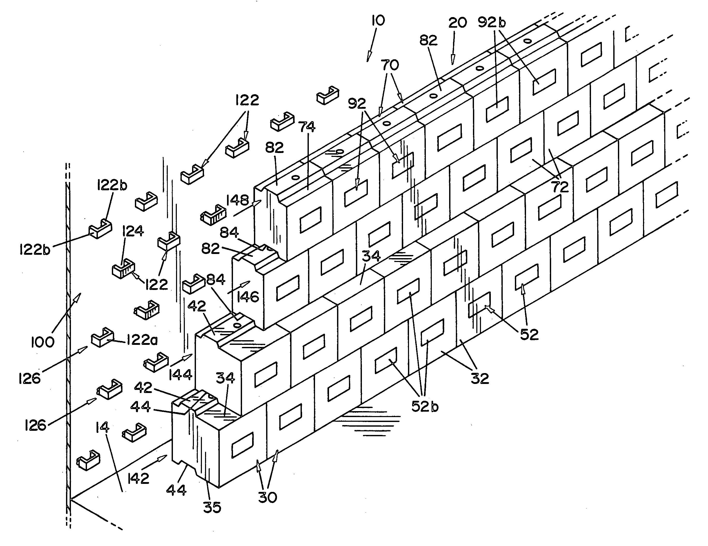
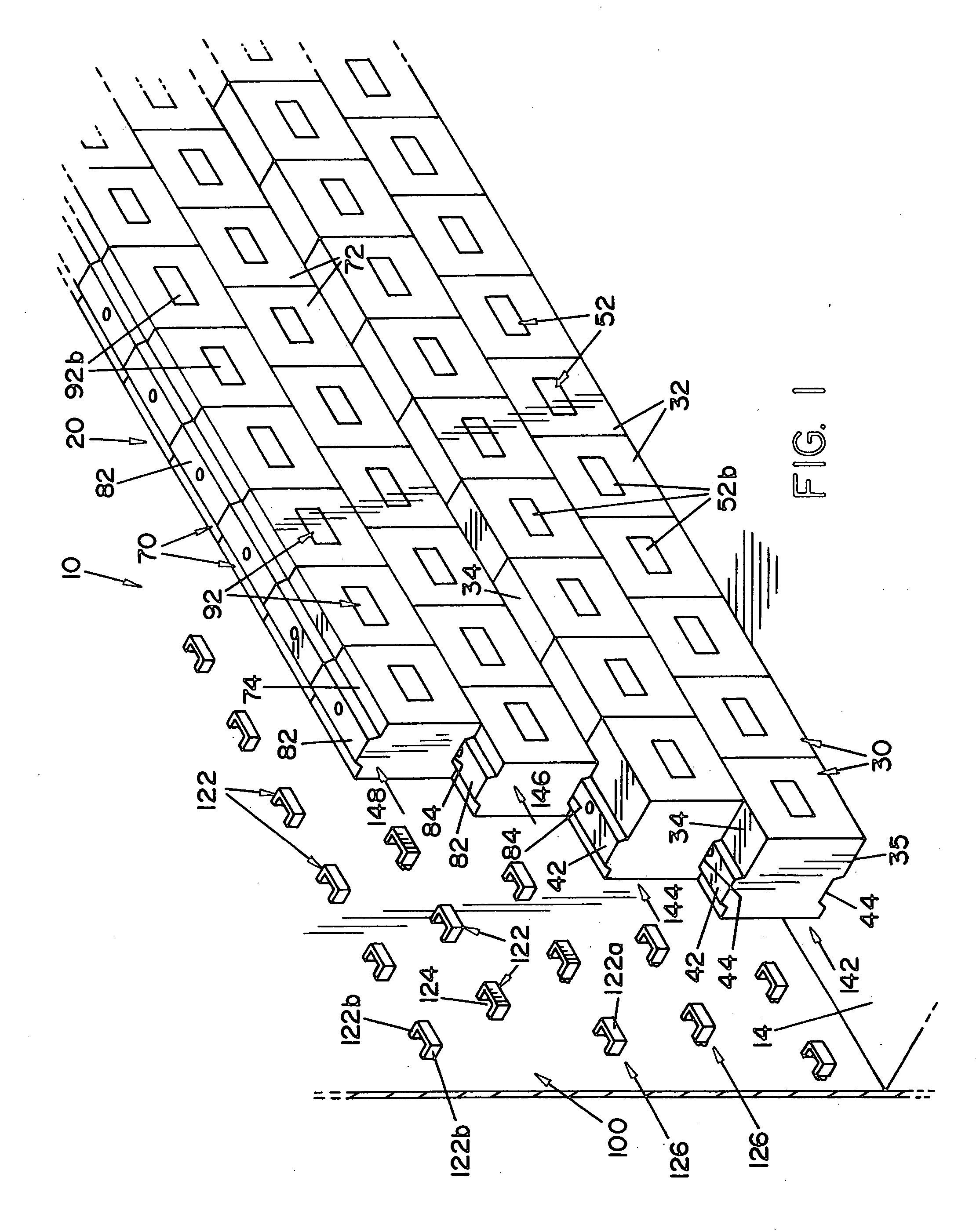
[0034] Referring now to the drawings wherein the showings are for the purpose of illustrating a preferred embodiment of the invention only, and not for the purpose of limiting same, FIG. 1 is a perspective view of a portion of a partially assembled furnace wall structure 10, illustrating a preferred embodiment of the present invention. Furnace wall structure 10 depicted in the drawings shows a refractory wall structure for use in a “clinker cooler” that cools hot clinker as it exits a furnace, such as a rotary kiln (not shown).

[0035] Furnace wall structure 10 is comprised of a refractory wall 20 and a metallic panel 100 that form the outer shell of the cooler structure. Refractory wall 20 is formed from refractory blocks 30, 70. In the embodiment shown, refractory wall 20 is comprised of two different refractory blocks, as shall be described in greater detail below.

[0036] Refractory wall 20 is spaced from metallic panel 100 to define a gap or space “X” therebetween, best seen in F...


PUM

PropertyMeasurementUnit
weightaaaaaaaaaa
refractoryaaaaaaaaaa
shapeaaaaaaaaaa

Abstract

A refractory block for forming a wall structure comprising a body of cast refractory material. The body has a front face, a back face, a top face, a bottom face, and two opposing side faces. The body further has a projection formed on the top face and a recess formed in the bottom face, the projection being dimensioned to be received within the recess such that a projection on a block can be received in a recess on a block thereabove. A refractory anchor is embedded within the body. The anchor has a portion extending from the body through the back face.

Description

FIELD OF THE INVENTION [0001] The present invention relates generally to the refractory arts, more particularly to a refractory block and refractory wall assembly. BACKGROUND OF THE INVENTION [0002] A clinker cooler is a structure designed to cool hot clinker that exits a furnace, such as a rotary kiln. Such coolers typically allow the clinker to cascade down a sloping path over grates through which cooling air is passed. [0003] The cooler structure is basically a metallic panel having an inner refractory block lining. Refractory blocks are stacked one on another to form a refractory wall that is spaced apart from the metallic panel. The refractory blocks that form the refractory lining are generally referred to as “cooler blocks,” and have heretofore been generally rectangular in shape having flat, outer surfaces. The blocks are formed from a cast refractory material having a metallic anchor, typically in the form of a U-shaped clip, cast within the block. A metallic, threaded rod ...

Claims


Application Information

Patent Timeline
Patent Type & Authority Applications(United States)
IPC IPC(8): E04H14/00E04F19/00
CPCE04B2/06E04B2002/0208E04C1/395F27D1/142F27D1/04F27D1/141F27D1/0006
Inventor STEPHANSKY, JOHN J.BERRY, JOHN E.
Owner HARBISON WALKER REFRACTORIES
Why Eureka
Try Eureka