Heat sink member and method of manufacturing the same

a technology of sink member and heat sink, which is applied in the direction of manufacturing tools, packaging, and so on, can solve the problems of enlargement of the thermal expansion coefficient of the cu/mo/cu clad member, and easy cracking or chapping of the same, etc., to suppress the enlargement of the thermal expansion coefficient, suppress the lowering of the thermal conductivity, and suppress the cracking and chapping.

Inactive Publication Date: 2006-11-02
NEOMAX MATERIALS
View PDF4 Cites 9 Cited by
  • Summary
  • Abstract
  • Description
  • Claims
  • Application Information

AI Technical Summary

Benefits of technology

[0006] The present invention has been proposed in order to solve the aforementioned problems, and an object of the present invention is to provide a heat sink member capable of suppressing d...

Problems solved by technology

However, Mo as the substrate is so hard and small in elongation that the same is easily cracked or chapped in the hot pressure welding or the cold pressure welding (cold rolling).
Particularly in the method cold-pressure-welding (cold-rolling) the Cu/Mo/Cu clad member, there is such inconvenience that the substrate consisting of Mo is easily cracked or chapped when rolling the substrate consisting of Mo and the ply members consisting of Cu and bonding the same to each other.
In the method bonding the substrate consisting of Mo and the ply members consisting of Cu to each other with the brazing filler metal consisting of the Mn—Ni—Cu alloy disclosed in the aforementioned Japanese Patent Laying-Open No. 11-2...

Method used


Image

  • Heat sink member and method of manufacturing the same
  • Heat sink member and method of manufacturing the same
  • Heat sink member and method of manufacturing the same

Examples


first embodiment

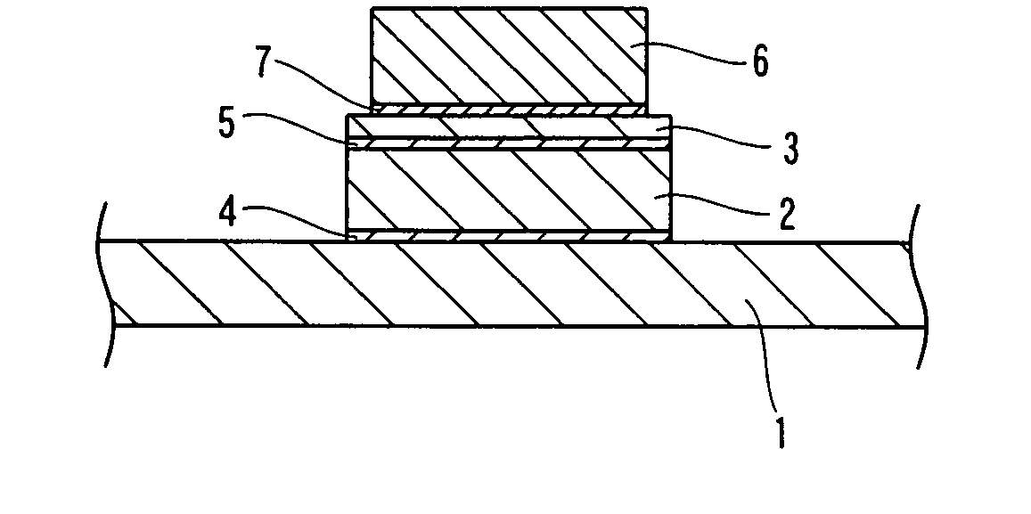
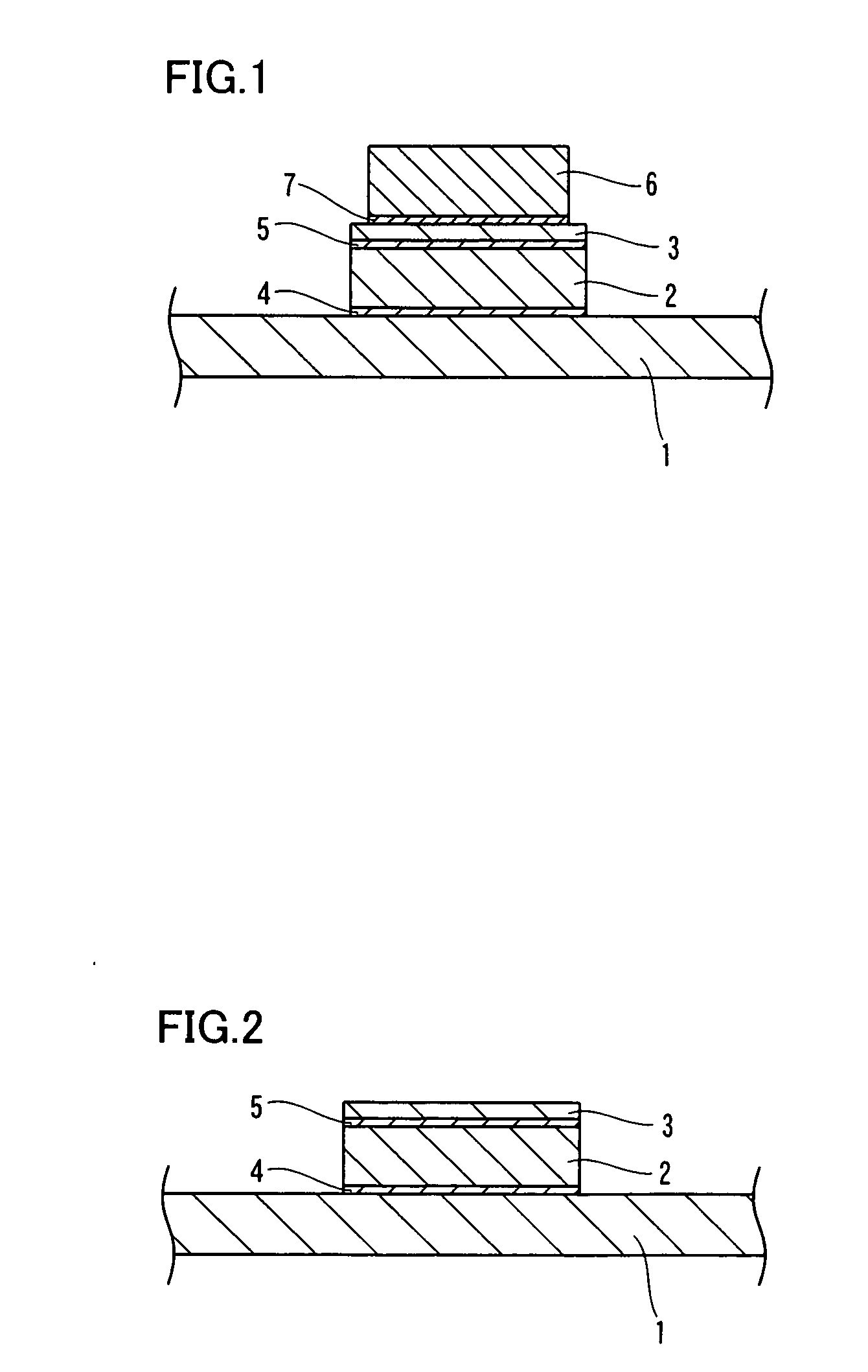
[0037]FIG. 1 is a sectional view showing a state of mounting a semiconductor element on a heat sink member according to a first embodiment of the present invention. FIG. 2 is a sectional view showing the heat sink member according to the first embodiment of the present invention. First, the structure of the heat sink member according to the first embodiment of the present invention is described with reference to FIGS. 1 and 2.

[0038] The heat sink member according to the first embodiment of the present invention includes a ply member 1 mainly composed of Cu (copper), a substrate 2 mainly composed of Mo (molybdenum) and another ply member 3 mainly composed of Cu (copper), as shown in FIG. 2. The ply member 1 and the ply member 3 are examples of the “first layer” and the “third layer” in the present invention respectively, and the substrate 2 is an example of the “second layer” in the present invention. The ply member 1, the substrate 2 and the ply member 3 have thicknesses of about 0...

second embodiment

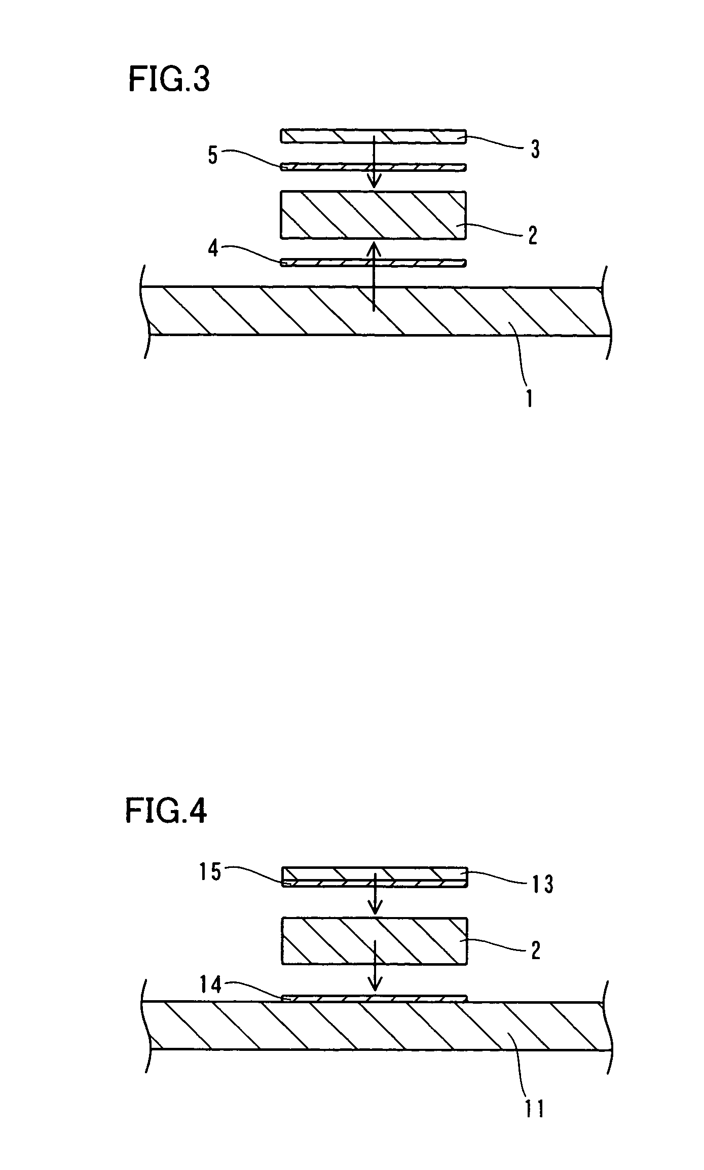
[0058] FIGS. 4 to 6 are sectional views for illustrating a method of manufacturing a heat sink member according to a second embodiment of the present invention. In this second embodiment, a method of manufacturing a heat sink member different from the aforementioned first embodiment is described.

[0059] In the method of manufacturing a heat sink member according to this second embodiment, ply members 11 and 13 shown in FIG. 4 are first formed by rolling a member mainly composed of Cu into a thickness of about 0.25 mm to about 7.5 mm and cutting the same into prescribed sizes. At this time, the ply member 13 is formed so that the length thereof is smaller than that of the ply member 11. Further, a member mainly composed of Mo (molybdenum) is formed to have a thickness of about 0.1 mm to about 3.0 mm by sintering. A substrate 2 is formed by cutting this member into a length substantially identical to that of the ply member 13.

[0060] Further, brazing layers 14 and 15 are formed by for...


PUM

PropertyMeasurementUnit
Percent by massaaaaaaaaaa
Thicknessaaaaaaaaaa

Abstract

A heat sink member capable of suppressing development of cracks and chaps in manufacturing, suppressing enlargement of a thermal expansion coefficient and suppressing lowering of thermal conductivity is obtained. This heat sink member comprises a ply member (1) mainly composed of Cu, a substrate (2) mainly composed of Mo and a brazing layer (4) consisting of an Sn—Cu alloy (Sn: 1 mass % to 13 mass %) arranged between the ply member and the substrate for bonding the ply member and the substrate to each other.

Description

TECHNICAL FIELD [0001] The present invention relates to a heat sink member and a method of manufacturing the same, and more particularly, it relates to a heat sink member employing Mo (molybdenum) and a method of manufacturing the same. BACKGROUND ART [0002] In general, a heat sink member employing molybdenum (Mo) is known as a heat sink member for absorbing heat generated from an electronic component or the like and radiating the same outward. A Cu / Mo / Cu clad member prepared by employing molybdenum as a substrate and cladding the same with Cu as ply members is known as this heat sink member employing molybdenum. In general, this Cu / Mo / Cu clad member is manufactured by hot pressure welding or cold pressure welding (cold rolling). However, Mo as the substrate is so hard and small in elongation that the same is easily cracked or chapped in the hot pressure welding or the cold pressure welding (cold rolling). Particularly in the method cold-pressure-welding (cold-rolling) the Cu / Mo / Cu ...

Claims


Application Information

Patent Timeline
IPC IPC(8): H01L23/34
CPCH01L23/3735H01L2224/32Y10T428/12903Y10T428/12826H01L2224/83101H01L2224/2612
Inventor SHIOMI, KAZUHIROISHIO, MASAAKIHASEGAWA, TSUYOSHI
Owner NEOMAX MATERIALS
Why Eureka
Try Eureka