Modulation device, demodulation device, modulation method and demodulation method

a technology of modulation device and modulation method, which is applied in the direction of phase-modulated carrier system, amplitude demodulation, modulation, etc., can solve the problems of increasing the demand for mobile communications, difficulty in reserving a desired radio communication path, and exhausting abundant frequency resources, so as to improve the signal transmission rate

Active Publication Date: 2006-11-02
PANASONIC CORP
View PDF9 Cites 8 Cited by
  • Summary
  • Abstract
  • Description
  • Claims
  • Application Information

AI Technical Summary

Benefits of technology

[0011] It is an object of the present invention to provide a modulation apparatus, demodulation apparatus, modulation method and demodulati...

Problems solved by technology

Such increasing demand for mobile communications will exhaust abundant frequency resources.
However, there are various difficulties in reserving a desired radio communication path in free space, especially space in outdoor environments.
Particularly, more difficulties arise under circumstances where terminals move at high s...

Method used


Image

  • Modulation device, demodulation device, modulation method and demodulation method
  • Modulation device, demodulation device, modulation method and demodulation method
  • Modulation device, demodulation device, modulation method and demodulation method

Examples


embodiment 1

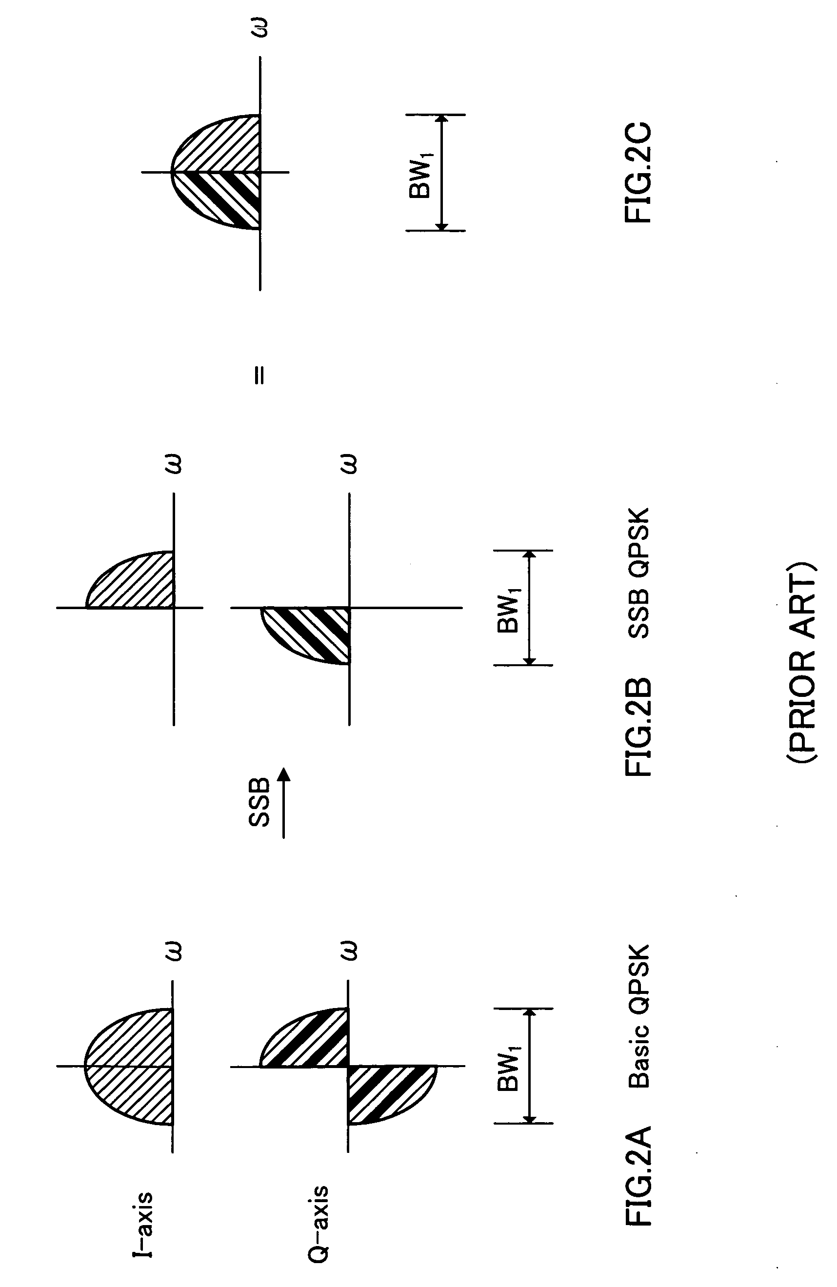
[0063]FIGS. 4A to 4D illustrate the concept of the modulation scheme of the invention. FIG. 4A illustrates spectra on the I axis and Q axis according to a conventional basic QPSK scheme. In order to improve double the transmission rate of the conventional QPSK scheme, frequency bandwidth BW1 should be doubled as shown in FIG. 4B, however the spectral efficiency is not improved. Therefore, in this embodiment, the SSB scheme is performed on the I-axis signal and Q-axis signal, each side bandwidth is thereby expanded to the whole frequency bandwidth BW1 that is two times the original side band (FIG. 4C), and each side band is multiplexed in the same frequencies (FIG. 4D). It is thus possible to implement communications with the double transmission rate while keeping the given frequency bandwidth. In other words, the transmission rate can be doubled as compared with SSB-QPSK described in Background Art as described above.

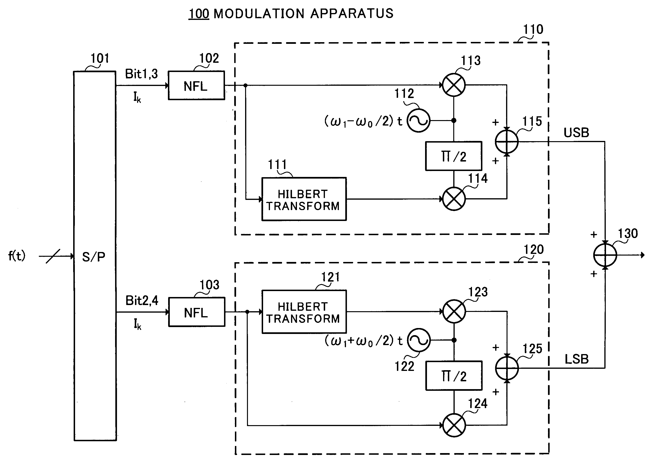
[0064]FIG. 5 illustrates a configuration to implement the concept...

embodiment 2

[0117] This Embodiment proposes a modulation scheme and demodulation scheme that improve the spectral efficiency more than in Embodiment 1.

[0118] First, before explaining a configuration of this Embodiment, compared are between a way of signal configuration in Embodiment 1 and a way of signal configuration in Embodiment 2.

[0119]FIGS. 17A to 17C illustrate the way of signal configuration in Embodiment 1. Modulation apparatus 100 of Embodiment 1 obtains the LSB signal with the spectrum as shown in FIG. 17A in second frequency-increasing SSB modulator 120, and the USB signal with the spectrum as shown in FIG. 17B in first frequency-increasing SSB modulator 110, combines the signals, and obtains a modulation signal with the spectrum as shown in FIG. 17C.

[0120] In contrast thereto, this Embodiment proposes forming a modulation signal (SSB-multiplexed modulation signal) with the spectrum as shown in FIG. 18. As can be seen from comparison between FIGS. 18 and 17C, by taking the signal ...

embodiment 3

[0184] The purely analog-based demodulation scheme as described in Embodiment 2 largely depends on the roll-off rate and roll-off filter, , and this method does not eliminate completely the inclusion of interfering components in a demodulated signal.

[0185] As can be seen from the spectrum in reception, the modulation scheme in Embodiment 2 provides a side band at the precisely same position as in the spectral configuration in OFDM.

[0186] By focusing attention on this respect, the inventors of the present invention found out that overlapping adjacent spectra can be completely eliminated by Fourier transform means.

[0187] This Embodiment proposes a demodulation scheme different from the demodulation scheme in Embodiment 2 on the model in the spectral configuration in Embodiment 2.

[0188]FIG. 21 illustrates a configuration of demodulation apparatus 600 of this Embodiment.

[0189] A received signal is input to band-pass filter (BPF) 601 in demodulation apparatus 600. The received signa...


PUM


Abstract

A modulation apparatus is disclosed that enables great improvements in signal transmission rate in a limited frequency band as compared with conventional modulation schemes. Modulation apparatus 100 has first and second frequency-increasing SSB modulators 110 and 120. The modulators 110 and 120 are configured to have respective carrier frequencies with a difference by a frequency corresponding to the reciprocal of the symbol rate (i.e. fundamental frequency of the input symbol). Adder 130 combines a LSB signal obtained from the SSB modulator 120 set for a higher carrier frequency, and a USB signal obtained from the SSB modulator 110 set for a lower carrier frequency to obtain a modulation signal.

Description

TECHNICAL FIELD [0001] The present invention relates to a modulation apparatus, demodulation apparatus, modulation method and demodulation method using SSB (Single Side Band) technique. BACKGROUND ART [0002] In recent years, with the widespread use of information processing technology and the rapid progression of the so-called IT (Information Technology) introduced society, the expansion and demand has been remarkable in information communications. For the communication infrastructure, introduction of wireless and high-speed communications is desired naturally to connect among the society, and further connect between a person and the society. Such increasing demand for mobile communications will exhaust abundant frequency resources. [0003] Currently, a main subject under study to enhance the spectral efficiency is improvements in technology relating to radio propagation as typified by MIMO (Multi Input Multi Output). However, there are various difficulties in reserving a desired rad...

Claims


Application Information

Patent Timeline
IPC IPC(8): H04L27/02H04L27/04H03D1/24H04L27/20H04L27/36
CPCH03C1/60H03D1/24H04B1/68H04L27/2338H04L27/06H04L27/2053H04L27/2332H04L27/04
Inventor OTA, GENICHIROIMAMURA, DAICHITAKAKUSAKI, KEIJIUESUGI, MITSURU
Owner PANASONIC CORP
Why Eureka
Try Eureka