Multi-fiber variable intensity wide-angle illuminator

a wide-angle illuminator and variable intensity technology, applied in the field of surgical instruments, can solve the problems of sub-optimal light refraction, wide-angle illuminators for ophthalmic surgery, and matching the light refracting index of vitreous eye fluid, and achieve the effect of reducing the damaging thermal effects of infrared radiation

Active Publication Date: 2006-11-02
ALCON INC
View PDF5 Cites 28 Cited by
  • Summary
  • Abstract
  • Description
  • Claims
  • Application Information

AI Technical Summary

Benefits of technology

[0008] The embodiments of the multi-fiber variable intensity wide-angle illuminator of the present invention substantially meet these needs and others. The various embodiments of the present invention provide for a reusable and for a disposable small gauge (e.g., 19, 20 or 25 gauge) optical fiber based endo-illuminator device for use in a surgical environment, such as vitreo-retinal / posterior segment surgery. Embodiments of the device can consist of a handle (e.g., Alcon-Grieshaber Revolution—DSP™ handle) connected to a small gauge cannula (e.g., 19, 20 or 25 gauge), wherein the inner dimension of the cannula can be used to house an optical fiber assembly comprising one or more, or a plurality of, fiber guides, each comprising one or more custom polymer optical fibers arranged in a specified geometry. The optical fiber assembly contained within the cannula can be connected via a handle mechanism, such as a simple push / pull mechanism, to the handle. The output from a light source, such as a xenon light source, can be optically coupled using standard SMA optical fiber connectors to the proximal end of the optical fiber assembly. The light source light output can be directly coupled to the optical fiber assembly, or an intermediary optical cable can be used between the light source and the optical fiber assembly. Either arrangement will allow for the efficient coupling of light from the light source, through the handle and emanating from the optical fiber assembly at the distal end of the cannula. The light source may be equipped with filters, known to those skilled in the art, to reduce the damaging thermal effects of infrared radiation originating from the light source. Activation of the handle mechanism, such as by a gentle and reversible squeezing action, can cause the fiber guides of the optical fiber assembly to diverge in a predetermined and adjustable manner at the distal end of the cannula. A simple mechanical locking mechanism, as will be known to those in the art, can be used to fix the illumination angle until released and / or readjusted by the user. Light emanating from the optical fiber assembly at the distal end of the cannula can be used to illuminate an area over a solid angle Ω, the angle Ω, being continuously adjustable by the operator via the handle.
[0011] To enable some of the advantages of the embodiments of this invention, the optical fiber assembly can be operably coupled to the handpiece to enable linear displacement of the optical fiber assembly within the cannula. The handpiece can include an adjustment means, such as a push / pull mechanism, for adjusting the linear displacement of the optical fiber assembly. Other adjusting means as known to those in the art can also be used including, for example, a mechanical coupling, an electrical coupling, a magnetic coupling, a pneumatic coupling or any combination thereof. The distal end (end closest to the surgical field) of the optical fiber assembly can be coincident with an open aperture of the cannula. Adjusting the linear displacement via the adjusting means can thus cause the optical fiber assembly to exit the open aperture by an amount corresponding to the change in linear displacement (a reverse adjustment can retract the optical fiber assembly). Further, a separator can be positioned between the fiber guides in such a way that the fiber guides can be uniformly displaced outward from one another by an amount proportional to the change in linear displacement from the distal end of the cannula. Alternatively, a material such as a memory shape alloy can be incorporated into the cladding of the fiber guides to effectuate the uniform displacement of the fiber guides as they exit the cannula distal end. In this way, the angle of illumination and the amount of illumination provided by the optical fiber assembly from the light beam to illuminate the surgical field (e.g. the retina of an eye) can be adjusted by the surgeon as needed. The embodiments of this invention can provide a range of illumination angles up to about 180° (e.g., 20° to about 180°).

Problems solved by technology

One disadvantage exhibited by some prior art wide-angle illuminators for ophthalmic surgery is a matching of the light refracting index of the vitreous eye fluid to that of the light refracting surface of the lens of the illuminator that comes in contact with the vitreous eye fluid.
Contact of the vitreous eye fluid with the light refracting surface of the light spreading lens of such prior art systems results in sub-optimal light refraction due to index switching caused by the vitreous eye fluid.
Another disadvantage of currently available wide-angle illuminators is glare.
Glare is unwanted stray radiation that provides no useful illumination, and either distracts an observer or obscures an object under observation.
A further disadvantage of typical prior art wide-angle illuminators is that they do not provide for varying the illumination angle and / or the intensity of the light source to adjust illumination for different conditions within the surgical field.
Further still, prior art wide-angle surgical illuminators are expensive to produce, a cost which is passed along to the surgeon and ultimately to the patient.
As a result, prior art illuminators are typically not disposable and will require periodic maintenance and sterilization between surgical procedures.

Method used


Image

  • Multi-fiber variable intensity wide-angle illuminator
  • Multi-fiber variable intensity wide-angle illuminator
  • Multi-fiber variable intensity wide-angle illuminator

Examples


Embodiment Construction

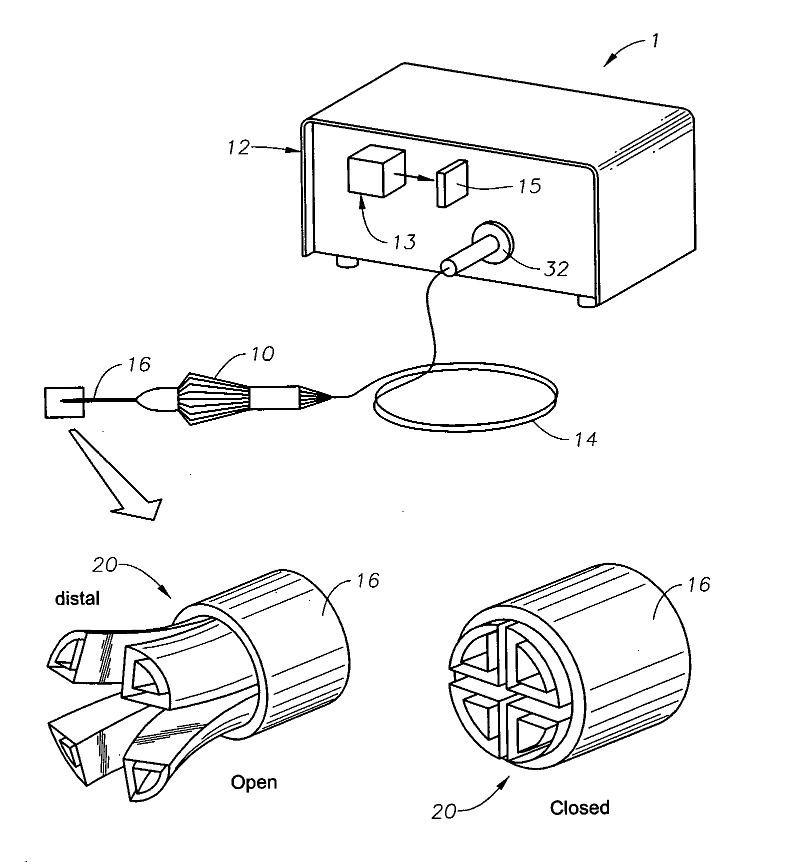
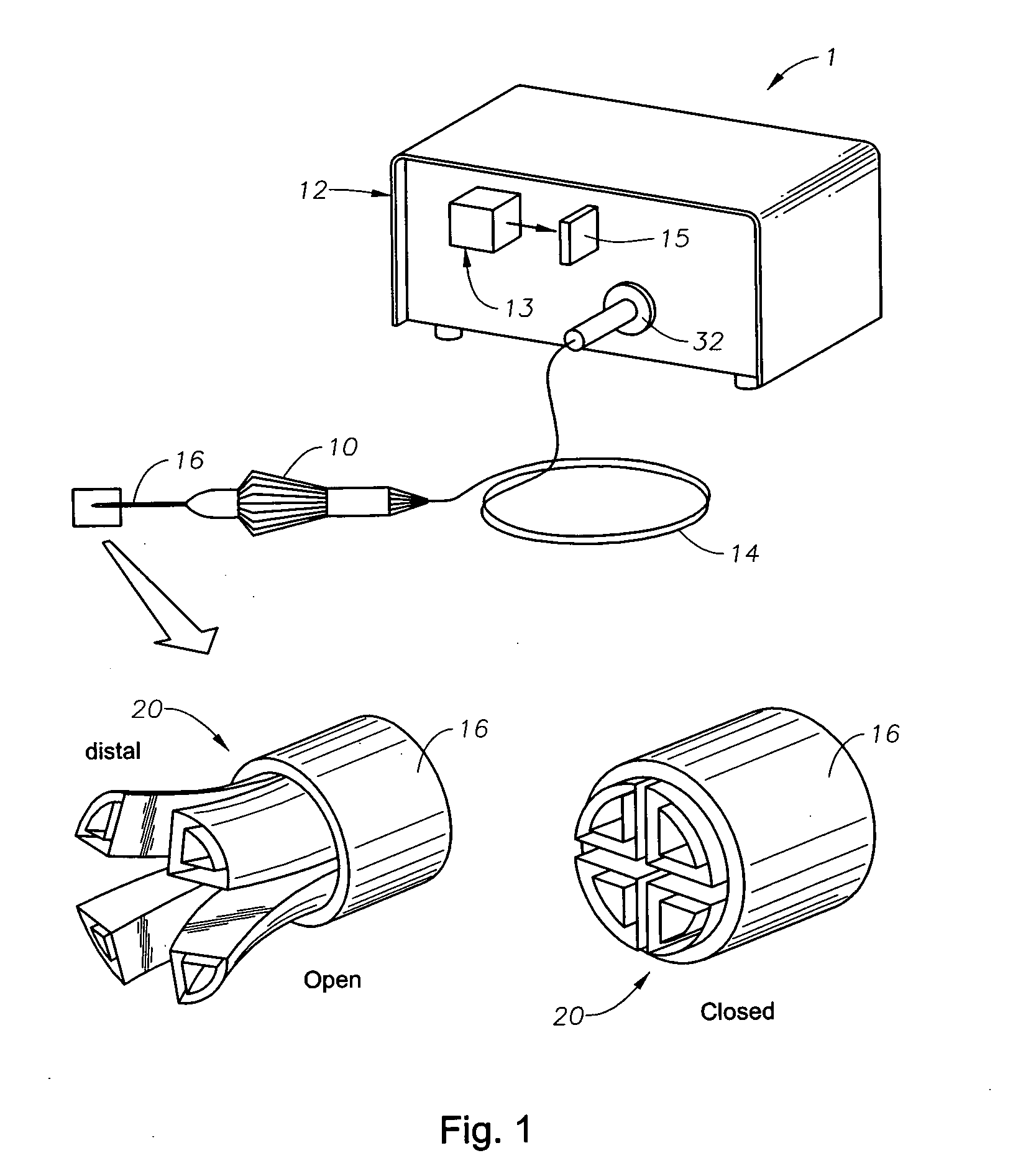
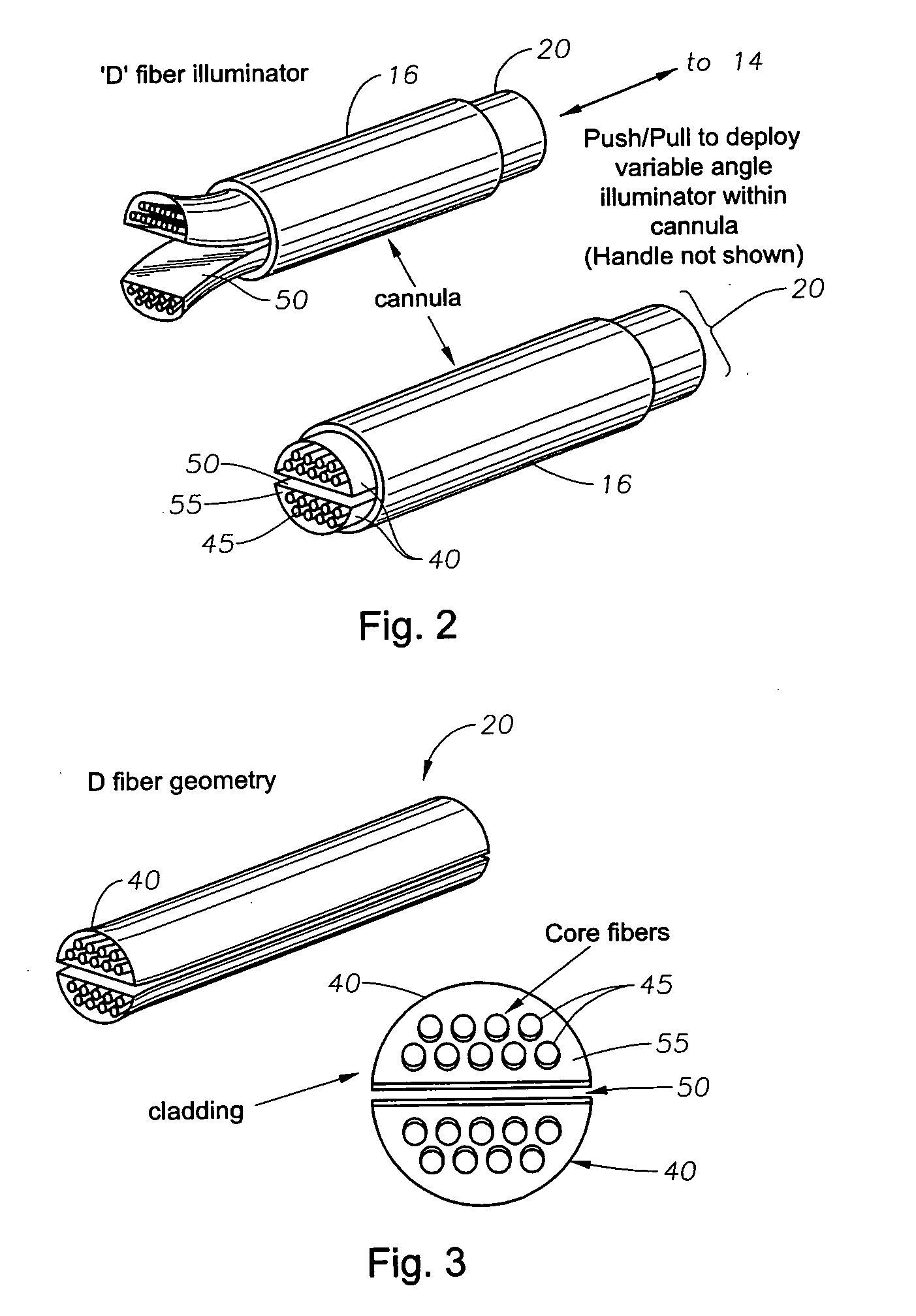
[0022] Preferred embodiments of the present invention are illustrated in the FIGURES like numerals being used to refer to like and corresponding parts of the various drawings.

[0023] The various embodiments of the present invention provide for a small gauge (e.g., 19, 20, or 25 gauge) optical fiber based endo-illuminator device for use in surgical procedures, such as in vitreo-retinal / posterior segment surgery. Embodiments of this invention can comprise a handpiece, such as the Alcon-Grieshaber Revolution—DSP™ handpiece sold by Alcon Laboratories, Inc., Fort Worth, Tex., connected to a small gauge cannula (e.g., 19, 20, or 25 gauge). The inner dimension of the cannula can be used to house an optical fiber assembly comprising a plurality of fiber guides and a means for separating the plurality of fiber guides, such as a separator, in accordance with the teachings of this invention. Embodiments of the multi-fiber wide-angle illuminator can be configured for use in the general field of...


PUM

PropertyMeasurementUnit
illumination anglesaaaaaaaaaa
acceptance angleaaaaaaaaaa

Abstract

An illuminator and surgical illumination system are disclosed, one embodiment of the surgical illumination system comprising: a light source for providing a light beam; an optical cable, optically coupled to the light source for receiving and transmitting the light beam; a handpiece operably coupled to the optical cable; an optical fiber assembly operably coupled to the handpiece, wherein the optical fiber assembly is optically coupled to the optical cable to receive and transmit the light beam and wherein the optical fiber assembly comprises a plurality of fiber guides, wherein each fiber guide comprises a cladding having one or more fiber cores for transmitting and scattering the light beam to illuminate the surgical field, and a cannula, operably coupled to the handpiece for housing and directing the optical fiber assembly. The surgical illumination system can further comprise a separator operable to maintain a spacing between the fiber guides. The optical fiber assembly, the cannula, and the handpiece can be fabricated from biocompatible materials. The optical fiber assembly can be operably coupled to the handpiece to enable linear displacement of the optical fiber assembly within the cannula. The handpiece can include an adjustment means, such as a push / pull mechanism, for adjusting the linear displacement of the optical fiber assembly. Other adjusting means as known to those in the art can also be used including, for example, a mechanical coupling, an electrical coupling, a magnetic coupling, a pneumatic coupling or any combination thereof. The distal end of the optical fiber assembly can be coincident with an open aperture of the cannula. Adjusting the linear displacement via the adjusting means can thus cause the optical fiber assembly to exit the open aperture by an amount corresponding to the change in linear displacement (a reverse adjustment can retract the optical fiber assembly). Further, a separator can be positioned between the fiber guides in such a way that the fiber guides can be uniformly displaced outward from one another by an amount proportional to the change in linear displacement from the distal end of the cannula.

Description

CROSS-REFERENCE TO RELATED APPLICATIONS [0001] This application claims priority under 35 U.S.C. §119 to U.S. Provisional Patent Application No. 60 / 676,201, filed Apr. 29, 2005, the entire contents of which are incorporated herein by reference.TECHNICAL FIELD OF THE INVENTION [0002] The present invention relates generally to surgical instrumentation. In particular, the present invention relates to surgical instruments for illuminating an area during surgery. Even more particularly, the present invention relates to a variable intensity, small gauge, wide-angle illuminator for illumination of a surgical field. BACKGROUND OF THE INVENTION [0003] In ophthalmic surgery, and, in particular, in vitreo-retinal surgery, it is desirable to use a wide-angle surgical microscope system to view as large a portion of the retina as possible. Wide-angle objective lenses for such microscopic systems exist, but they require a wider illumination field than that provided by the cone of illumination of a ...

Claims


Application Information

Patent Timeline
Patent Type & Authority Applications(United States)
IPC IPC(8): G02B6/04F21Y101/00
CPCA61B1/00165Y10S362/804A61F9/00A61B2019/5206G02B6/0008A61B2090/306A61B3/0008A61B1/0627
Inventor CAZZINI, KARL
Owner ALCON INC
Why Eureka
Try Eureka