Power transmission system

Inactive Publication Date: 2006-11-02
TOYOTA CENT RES & DEV LAB INC
View PDF12 Cites 95 Cited by
  • Summary
  • Abstract
  • Description
  • Claims
  • Application Information

AI Technical Summary

Benefits of technology

[0008] An advantage of the present invention is that, in a power transmission system which can transmit power of an engine to a load via both of a speed variator and a gearing mechanism provided in parallel to one another, distribution of power transmitted to the speed variator and power transmitted to the gearing mechanism can be actively controlled, such that the speed variator capacity can be reduced while also enhancing power transmission efficiency.
[0009] A power transmission system according to the present invention comprises a first power transmitting section capable of transmitting power from an engine to a load via a speed variator while changing speed, a second power transmitting section capable of transmitting power from the engine to the load via a gearing mechanism provided in parallel to the speed variator, a prime mover that generates torque which can be controlled, and a control unit that controls torque of the prime mover. The gearing mechanism is a mechanism capable of performing a torque combining operation in which torque from the engine and torque from the prime mover are combined in a state such that their torque ratio equals a first predetermined ratio, and the combined torque is transmitted to the load. When power transmission between the engine and the load is performed via both the speed variator and the gearing mechanism, the control unit performs power distribution control for controlling distribution of power conveyed to the speed variator and power conveyed to the gearing mechanism by adjusting torque of the prime mover.
[0010] According to another aspect, the present invention provides a power transmission system comprising a first power transmitting section capable of transmitting power from an engine to a load via a speed variator while changing speed, a second power transmitting section capable of transmitting power from the engine to the load via a gearing mechanism provided in parallel to the speed variator, a driven machinery that generates torque which can be controlled, and a control unit that cont

Problems solved by technology

For this reason, it is not possible to actively control the power transmitted to the planetary gear mechanism in a manner independent from the speed changing control of the speed variator.
As such, according to systems described in patent documents 1 and 2 and non-patent docum

Method used


Image

  • Power transmission system
  • Power transmission system
  • Power transmission system

Examples


first embodiment

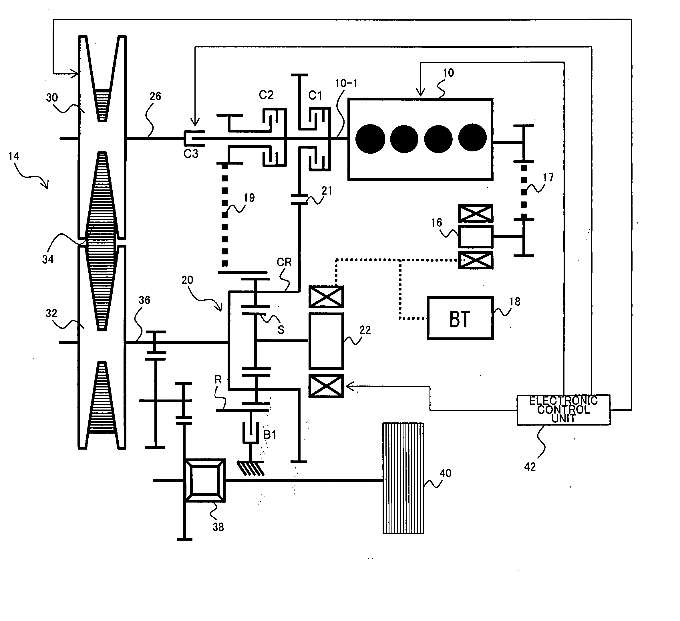
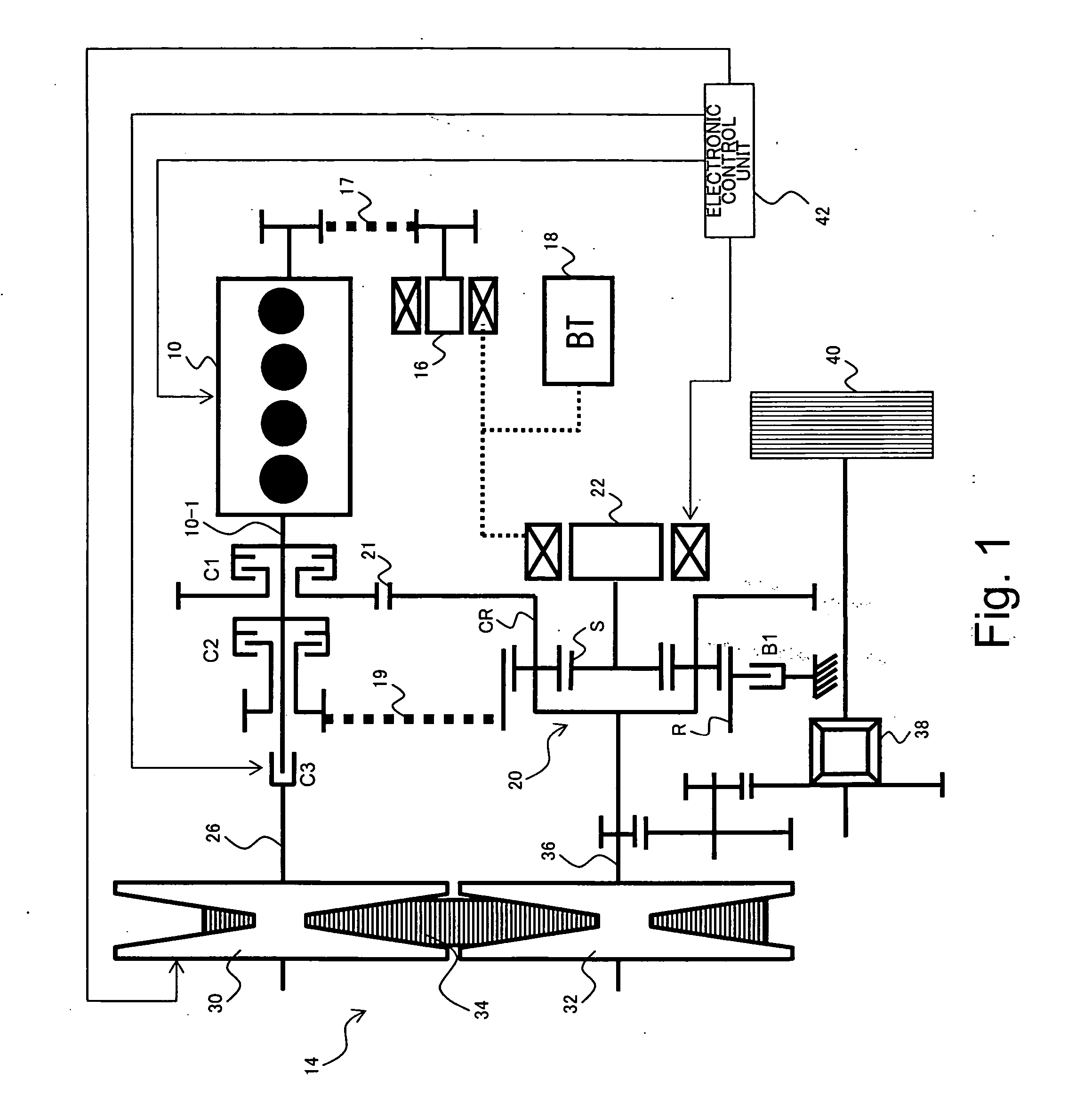
[0097]FIG. 1 is a diagram showing a general configuration of a power output system including a power transmission system according to a first embodiment of the present invention. The power output system according to the present embodiment is a hybrid-type power output system, and comprises an engine 10, speed variator 14, starter generator 16, battery 18, planetary gear mechanism 20, motor generator 22, electronic control unit 42, clutches C1, C2, C3, and brake B1, which are described below. In the power output system according to the present embodiment, while power from the engine 10 can be transmitted to a load via the speed variator 14 which changes speed, power from the engine 10 can also be transmitted to the load via the planetary gear mechanism 20. The power output system according to the present embodiment is used in a drive system of a vehicle, for example.

[0098] Power generated by the engine 10 can be transmitted to an input shaft 26 of the speed variator 14 via the clutc...

second embodiment

[0137]FIG. 22 is a diagram showing a general configuration of a power output system according to a second embodiment of the present invention. In contrast to the first embodiment, the planetary gear mechanism 20 provided in parallel to the speed variator 14 in the present embodiment is configured with a Ravigneaux type planetary gear mechanism, in which the carrier and the ring gear are shared by a single-pinion type planetary gearset and a double-pinion type planetary gearset. This Ravigneaux type planetary gear mechanism includes, as the rotating elements, sun gears SA and SB, carrier CR, and ring gear R. The sun gears SA and SB are capable of coupling to the motor generator 22 via clutches C5 and C4, respectively, and torque can be transmitted from the motor generator 22 to the sun gears SA, SB. The ring gear R is capable of coupling to the output shaft 10-1 of the engine 10 via a transmission device 19 such as a chain and via the clutch C2. The carrier CR is coupled to the outpu...

third embodiment

[0169]FIG. 42 is a diagram showing a general configuration of a power output system according to a third embodiment of the present invention. In contrast to the first embodiment, the clutch C1 of the present embodiment is capable of effecting and decoupling the coupling between the output shaft 10-1 of the engine 10 and the carrier CR (driven wheel 40) via a transmission device 25. The transmission device 25 may be composed with a chain or the like, and is provided in parallel to the speed variator 14. As such, in the present embodiment, there is provided a third power transmission path by which power from the engine 10 can be transmitted to the driven wheel 40 via the clutch C1 and the transmission device 25 at a predetermined gear ratio. As other structures of the third embodiment are identical to those of the first embodiment, description of those structures will not be repeated below.

[0170] Operations performed by the power output system according to the present embodiment are ...


PUM


Abstract

In a power transmission system for transmitting power of an engine to a load, a planetary gear mechanism provided in parallel to a speed variator combines torque conveyed from the engine with torque conveyed from a motor generator in a state such that their torque ratio equals a predetermined ratio, and transmits the combined torque to a driven wheel. When performing power transmission between the engine and the driven wheel via both the speed variator and the planetary gear mechanism, power distribution between the power conveyed to the speed variator and the power conveyed to the planetary gear mechanism can be actively controlled by adjusting the torque of the motor generator. As a result, the speed variator capacity can be reduced while enhancing power transmission efficiency.

Description

PRIORITY INFORMATION [0001] This application claims priority to Japanese Patent Applications No. 2005-132880 filed on Apr. 28, 2005 and No. 2006-095776 filed on Mar. 30, 2006, which are incorporated herein by reference in their entireties. BACKGROUND OF THE INVENTION [0002] 1. Field of the Invention [0003] The present invention relates to a power transmission system for transmitting power between an engine and a load. [0004] 2. Description of the Related Art [0005] Power transmission systems of this type are disclosed in Japanese Translated Publications for PCT No. 2002-513118 (hereinafter referred to as patent document 1) and No. 2002-543340 (patent document 2), and Shuiwen Shen, Alex Serrarens, Maarten Steinbuch, Frans Veldpaus, “Coordinated Control of a Mechanical Hybrid Driveline with a Continuously Variable Transmission”, JSAE Review 22, 2001, pp. 453-461 (non-patent document 1). According to these documents, a planetary gear mechanism is provided in parallel to a continuously ...

Claims


Application Information

Patent Timeline
IPC IPC(8): F16H37/02F16H3/72B60K6/365B60K6/44B60K6/445B60K6/543B60L50/16B60W10/00B60W10/04B60W10/06B60W10/08B60W10/10B60W10/105B60W10/11B60W10/115B60W20/00F02D29/00F02D29/02F16H61/02F16H61/68F16H61/684F16H61/686F16H63/50
CPCB60K6/365Y10T477/23B60K6/445B60K6/543B60W10/06B60W10/08B60W10/107B60W20/00F16H3/728F16H37/022F16H2037/088Y02T10/6286Y02T10/6239Y10T477/6217B60K6/387Y02T10/62B60W20/11
Inventor WATANABE, TAKAONISHIZAWA, HIROYUKIOSAWA, MASATAKA
Owner TOYOTA CENT RES & DEV LAB INC
Why Eureka
Try Eureka