Machine and method for converting a linear input to a rotational output

a linear input and output technology, applied in the direction of belts/chains/gearings, motors, etc., can solve the problems of ineffective utilization of gravity, devices that do not operate in a manner, and existing devices such as those described above, and achieve the effect of efficient utilization of gravity

Inactive Publication Date: 2006-11-09
KUNNAS RICHARD
View PDF11 Cites 20 Cited by
  • Summary
  • Abstract
  • Description
  • Claims
  • Application Information

AI Technical Summary

Benefits of technology

[0005] A machine for converting a linear input to a rotary output is provided comprising: a rotatable member, an extendable and retractable member coupled to the rotatable member for rotation therewith, and a control that extends and retracts the extendable and retractable member during rotation of the rotatable member generally in relation to the angular position of the extendable and retractable member while tending to maintain the potential energy of the extendable and retractable member during at least part of extension and retraction.

Problems solved by technology

Existing devices, such as those described above, generally tend to require a significant amount of energy to operate due to the substantial frictional resistance inherent in such designs.
Further, such devices do not operate in a manner that results in efficient utilization of gravity to produce a rotational output.

Method used


Image

  • Machine and method for converting a linear input to a rotational output
  • Machine and method for converting a linear input to a rotational output
  • Machine and method for converting a linear input to a rotational output

Examples


Embodiment Construction

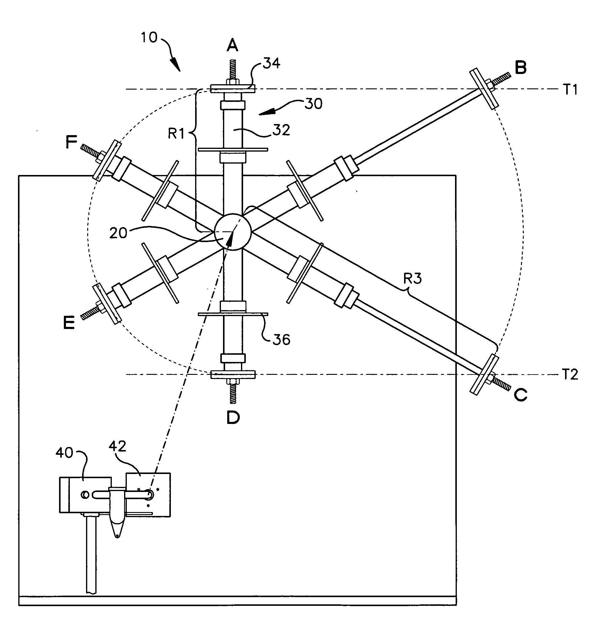
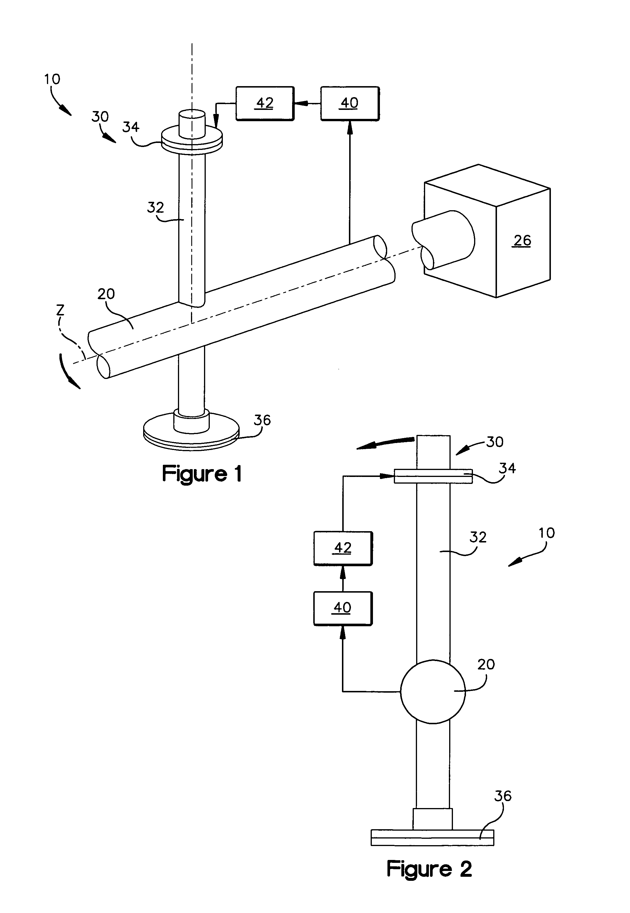
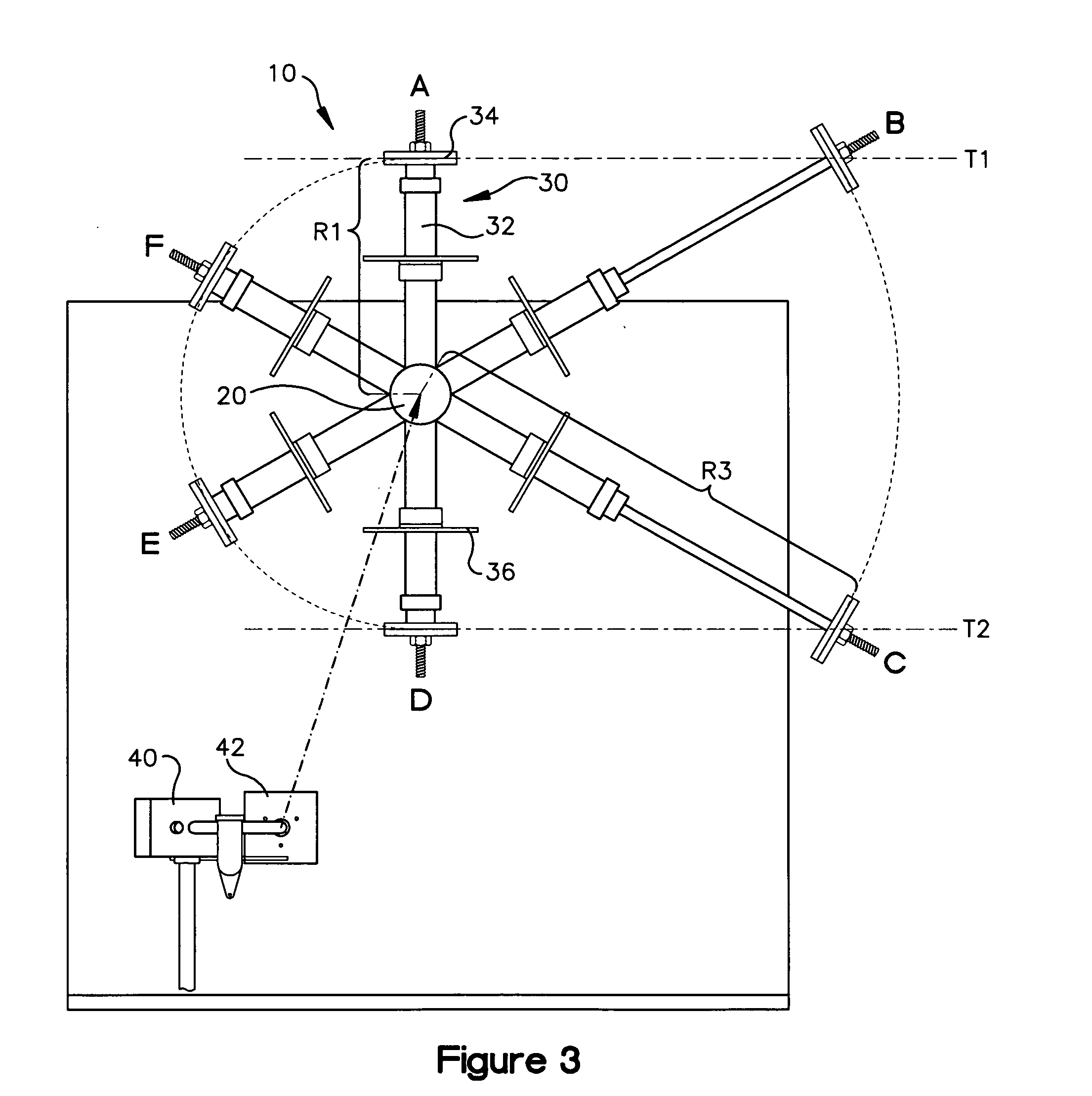
[0018] For the sake of facilitating this detailed description of the invention the approximate rotational positions are described relative to the typical twelve hours shown on the face of a clock. Six o'clock is oriented in the downward direction and twelve o'clock is oriented in the upward direction. Therefore, it will be appreciated that with this orientation, the six o'clock direction is the direction of the force of gravity.

[0019] Further, as used herein the term “upward sweep” refers to rotational movement in a direction opposed to the direction of the force of gravity. Similarly, with this orientation, 0 degrees corresponds to the 12 o'clock position and 180 degrees corresponds to the 6 o'clock position The term “downward sweep” refers to rotational movement in a direction coincidental to the direction of the force of gravity. Rotational movement from twelve o'clock to six o'clock, clockwise or counterclockwise is a downward sweep. Rotational movement from six o'clock to twel...


PUM


Abstract

The invention is a device that converts a linear input to a rotational output. The invention includes a system of one or more extendable and retractable members that actively change the radius of rotation of weights on the members. The members are connected to a rotatable member for rotation about a non-vertical axis. By actively changing the radius of rotation of a weight, a non-circular path is established for each weight to follow. This path is biased so that, while the weight has the greatest radius of rotation, it also is undergoing a downward stroke. While the weight is undergoing an upward stroke, the radius of rotation is at its minimum. The system thereby utilizes the force of gravity during transitions between maximum and minimum radii to produce a rotational output.

Description

FIELD OF THE INVENTION [0001] The present invention relates generally to rotational machines and devices and more particularly to a gravity operated or assisted machine for supplying, conserving, and / or recovering energy, for example for the purpose of rotating a shaft. BACKGROUND [0002] A variety of different devices utilizing gravity to produce a rotary output have been invented. Typically, such devices include one or more weights arranged on movable members and coupled for rotation with a rotating shaft. For example, in U.S. Pat. No. 6,694,844 to Love (“Love”) an apparatus to recover energy through gravitational force is disclosed having a wheel-like, connected, encircling surface, including an axially horizontal track which has an interior surface which weighted objects contact and are carried around the interior surface. The interior surface is a connected, encircling, wheel-like surface, is not a round circle or a cylinder, but has an offset center of rotation closest to a sid...

Claims


Application Information

Patent Timeline
Patent Type & Authority Applications(United States)
IPC IPC(8): F16H27/04
CPCF03G3/00Y10T74/18536F03G7/10F03G7/00F03G7/0252F03G7/107
Inventor KUNNAS, RICHARD
Owner KUNNAS RICHARD
Why Eureka
Try Eureka