
Generating guiding patterns for directed self-assembly

a lithographic pattern and self-assembly technology, applied in the direction of photomechanical equipment, cad circuit design, instruments, etc., can solve the problems of kinks that reset the self-assembly process, the overall cost of multiple patterning techniques has reached a level that other techniques may need to be explored, and the long-range pattern appears somewhat chaoti

Active Publication Date: 2015-05-12
SIEMENS PROD LIFECYCLE MANAGEMENT SOFTWARE INC
View PDF4 Cites 6 Cited by
  • Summary
  • Abstract
  • Description
  • Claims
  • Application Information

AI Technical Summary

Benefits of technology

The patent is about a way to make some structures using a process called self-assembly. The process uses a backbone structure and a simple equation to determine where the structure should be. The technique is called elastic potential energy, and it helps create things like holes or gaps in a material. The patent text will explain how this technique can be used to make things like microelectronic devices.

Problems solved by technology

While multiple patterning techniques provide the resolution required for further scaling, the overall cost to implement multiple patterning techniques has reached a level that other techniques may need to be explored.
One problem with these polymers is that, although local order and roughness can be quite good, small variations in the polymer chain can lead to kinks that reset the self-assembly process.
Long range patterns therefore appear somewhat chaotic.
However, DSA has its own set of challenges that need to be addressed before becoming a viable alternative to current lithographic techniques.

Method used


Image

  • Generating guiding patterns for directed self-assembly
  • Generating guiding patterns for directed self-assembly
  • Generating guiding patterns for directed self-assembly

Examples


Embodiment Construction

[0024]Various aspects of the present invention relate to techniques of generating guiding patterns for via-type feature groups. In the following description, numerous details are set forth for purpose of explanation. However, one of ordinary skill in the art will realize that the invention may be practiced without the use of these specific details. In other instances, well-known features have not been described in detail to avoid obscuring the present invention.

[0025]Although the operations of some of the disclosed methods, apparatus, and systems are described in a particular, sequential order for convenient presentation, it should be understood that this manner of description encompasses rearrangement, unless a particular ordering is required by specific language set forth below. For example, operations described sequentially may in some cases be rearranged or performed concurrently. Moreover, for the sake of simplicity, the attached figures may not show the various ways in which t...


PUM


Abstract

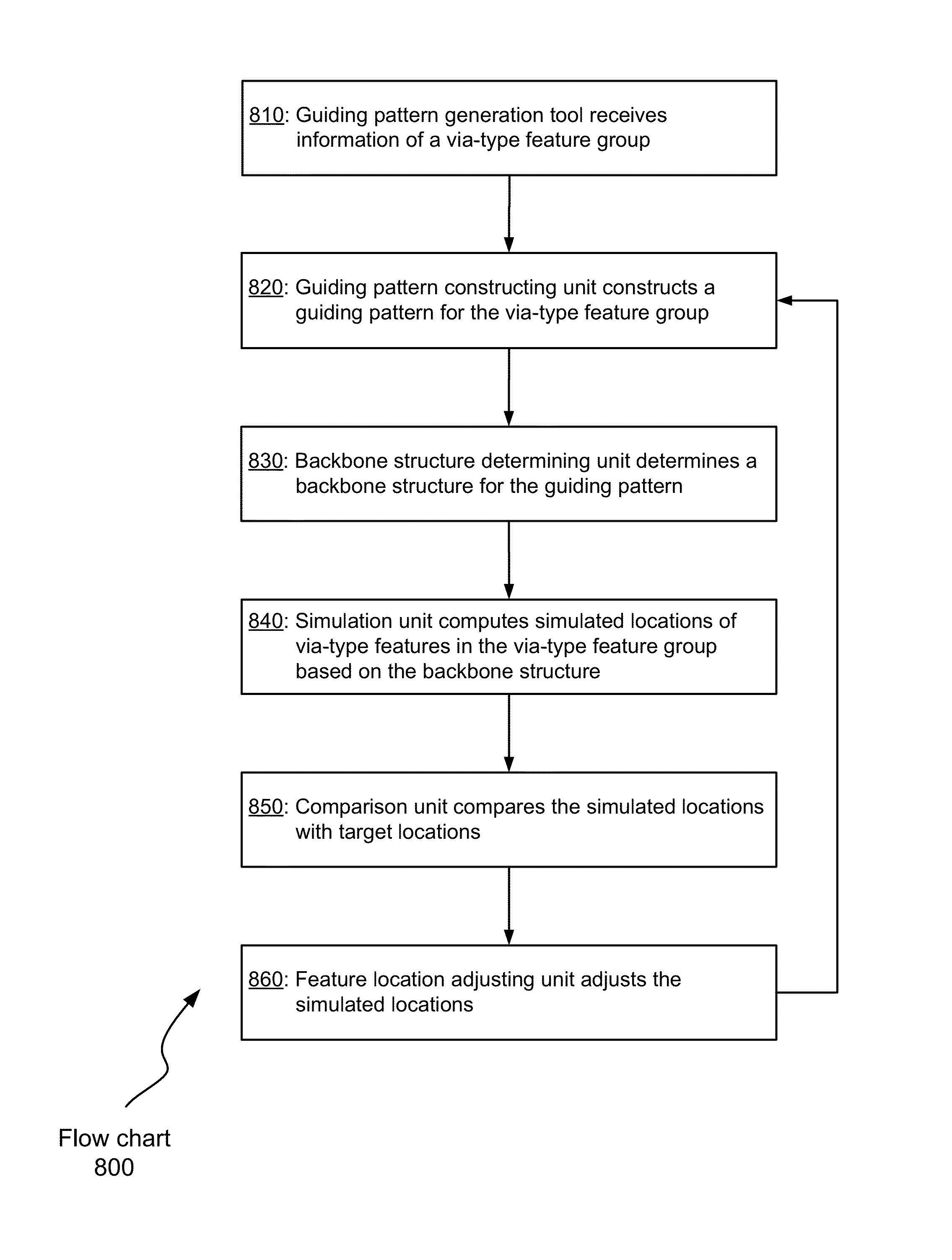
Aspects of the invention relate to techniques of generating guiding patterns for via-type feature groups. A guiding pattern may be constructed for a via-type feature group that comprises two or more via-type features in a layout design. A backbone structure may then be determined for the guiding pattern. Based on the backbone structure and a self-assembly model, simulated locations of the two or more via-type features are computed. The simulated locations are compared with targeted locations. If the simulated locations do not match the targeted locations based on a predetermined criterion, the simulated locations adjusted to derive modified locations. Using the modified locations, the above operations may be repeated until the simulated locations match the targeted location based on a predetermined criterion or for a predetermined number of times.

Description

FIELD OF THE INVENTION[0001]The present invention relates to photolithographic processing technologies. Various implementations of the invention may be particularly useful for directed self-assembly lithographic patterning.BACKGROUND OF THE INVENTION[0002]Conventional lithographic imaging processes employ liquid immersion to increase the effective numerical aperture (NA) and make use of extensive resolution enhancement techniques (RET). This appears adequate to meet the lithographic needs of integrated circuits through the 32 nm generation. Starting from the 22 nm node, the numerical aperture NA has only marginally increased and the k1 value is approaching the theoretical limit of 0.25. Further lithography scaling has been relied mainly on double or even multiple patterning techniques. While multiple patterning techniques provide the resolution required for further scaling, the overall cost to implement multiple patterning techniques has reached a level that other techniques may nee...

Claims


Application Information

Patent Timeline
Patent Type & Authority Patents(United States)
IPC IPC(8): G06F17/50G06F11/22
CPCG06F17/5072G06F17/5081G03F7/0002G06F30/39
Inventor ROBLES, JUAN ANDRES TORRESGRANIK, YURISAKAJIRI, KYOHEI
Owner SIEMENS PROD LIFECYCLE MANAGEMENT SOFTWARE INC
Learn More