
Enriched high conductivity geothermal fill and method for installation

Inactive Publication Date: 2006-11-09
SPADAFORA PAUL F +2
View PDF10 Cites 32 Cited by
  • Summary
  • Abstract
  • Description
  • Claims
  • Application Information

AI Technical Summary

Benefits of technology

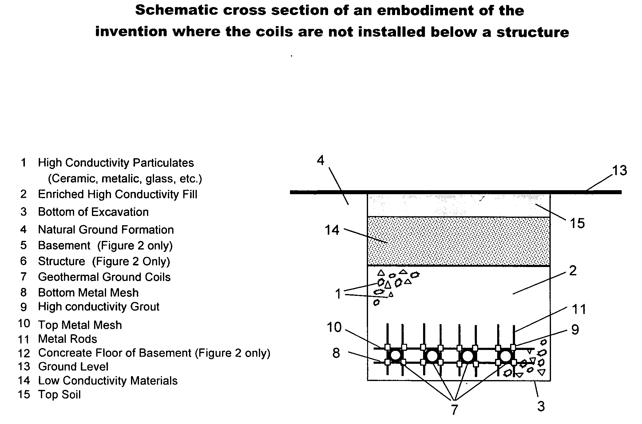
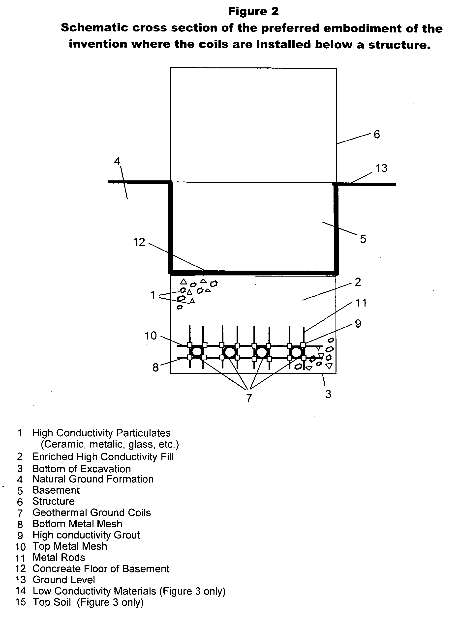
[0011] Loss of ground heat to the cold atmosphere in the winter and gain of ground heat by the hot atmosphere in the summer is reduced by the use of a layer of low heat conductivity (1.0 W / m.K or lower) material above the geothermal ground coil field or by installing the coils below a structure. Installation costs are reduced by taking advantage of excavations already made for below ground floors, basements or any other independent reason instead of requiring a completely separate and dedicated excavation for the installation of the geothermal ground coils.
[0012] Using the teachings of our invention, the heat transfer of the ground in contact with and in the vicinity of the ground coils is greatly improved and the heat recovery is greatly increased, thereby minimizing or completely eliminating the need for supplemental electric heating, improving efficiency and the capacity of the system and reducing capital and operating cost for both heating and cooling.

Problems solved by technology

All of the referenced patents suffer from the shortcoming that they do not address the most common limiting factor in geothermal systems during the heating season, which is the inability of the ground, in contact and in the immediate vicinity of the ground coils, to readily recover the heat that is transferred to the fluid in the coils.
This causes the ground temperature in the vicinity of the coils to be lowered, which in turn reduces the capacity and the efficiency of the system.
The referenced patents also do not address the most common limiting factor during the cooling season, which is the inability of the ground in contact and in the vicinity of the coils to dissipate the heat transferred from the liquid in the coils.
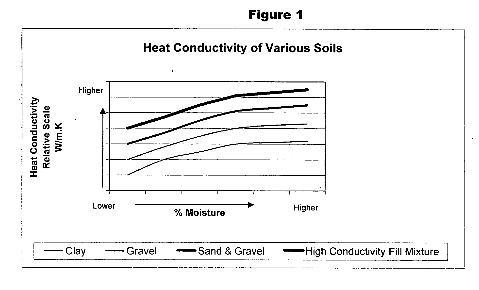
These limiting factors are directly related to the heat conductivity of the ground.
During the coldest periods of the year, the heat load obviously increases and the heat removal requirement from the ground in contact with the geothermal coils also increases but the natural heat recovery by the ground surrounding the coil is too slow to maintain the normal ground temperature which becomes the limiting factor for the entire geothermal system.
This phenomenon lowers the ground temperature near the coil and in turn lowers the temperature of the circulating fluid which reduces the heating capacity of the geothermal system.
The energy costs increase because of the auxiliary electric heating requirements.
This greatly reduces the return on investment used to justify the geothermal system.
Higher conductivity of the fill results in rapid heat recovery in the heating season and rapid heat dissipation during the cooling season of the fill in the vicinity of the coils.
Theoretically the deeper the bore holes or the deeper the excavation the warmer the ground temperature, however the drilling costs or the excavation costs to install the ground coils will increase with the depth.

Method used


Image

  • Enriched high conductivity geothermal fill and method for installation
  • Enriched high conductivity geothermal fill and method for installation
  • Enriched high conductivity geothermal fill and method for installation

Examples


Embodiment Construction

[0017] Materials that are tested to have higher heat conductivity properties than natural ground formation, which can be lower than 1.0 W / m.K, and that have the proper chemical, physical and drainage characteristics to make them suitable for ground fill are used in combination with each other and natural good conductivity ground fill to cover and encapsulate geothermal ground coils installed in excavations. Improving the conductivity of the fill that covers and encapsulates the coils to above 1.5 w / m.K, will improve the heat transfer rate from the bulk of the ground to the fluid inside the coils, and more importantly, increase the rate of heat recovery of the fill in the vicinity of the ground coils. This minimizes or eliminates the need for supplemental electric heating coils, improving the overall efficiency of the geothermal heating system.

[0018] In the summer when cooling is required, the higher conductivity fill improves the rate of heat removal from the fill around the ground...


PUM

PropertyMeasurementUnit
Thermal conductivityaaaaaaaaaa

Abstract

A geothermal fill material composed of one or more high heat conductivity materials alone or in combination to produce a fill that can be used to cover and encapsulate geothermal ground coils to improve heat transfer between the ground and the fluid inside the coils and to improve the rate of heat recovery of the fill in contact and in the vicinity of the coils. These materials can be in the form of particulates, rods or wire mesh and in any combination. Further enhancements are to cover this high conductivity material with low conductivity materials near the surface of the ground or to install the coils in a ground coil field below a structure in order to reduce ground heat loss to the atmosphere in the winter and to reduce heat gain from the atmosphere in the summer.

Description

REFERENCES CITED [REFERENCES BY][0001]U.S. Patent Documents5,477,914December 1995Rawlings165 / 455,533,355July 1996Rawlings165 / 455,738,164April 1998Hilderbrand165 / 456,251,179June 2001Allan106 / 719FIELD OF INVENTION [0002] The present invention relates to heat recovery systems and methods, and more particularly pertains to a system and method whereby the fill used to cover and surround geothermal coils is used in combination with high heat conductivity materials to improve heat transfer and heat recovery from the ground. BACKGROUND OF THE INVENTION [0003] Several prior art patents have utilized the earth as a source of heat and as a heat sink. Commercial geothermal energy systems are available and have been in use for several years. These systems normally utilize a water feed heat pump for both heating and cooling. The circulating fluid that feeds the heat pump flows through tubes that are buried deep in the ground and the circulating fluid uses the ground surrounding the tubes as both ...

Claims


Application Information

Patent Timeline
IPC IPC(8): F24J3/08
CPCF24J3/081Y02E10/12F28F13/00F28D20/0052C04B2111/00663C04B2111/00706F24T10/10Y02E10/10
Inventor SPADAFORA, PAUL F.SPADAFORA, RONALD M.SPADAFORA, FRANK E.
Owner SPADAFORA PAUL F
Learn More