Ultrasonic induced crack propagation in a brittle material

a brittle material and ultrasonic technology, applied in the field of separation of a sheet of brittle material, can solve the problems of significant energy added to the sheet, slow separation, unsuitable for certain configurations or manufacturing processes of the material, etc., and achieve the effect of reducing the introduction of disturbances into the ribbon and reducing twisting

a brittle material and ultrasonic technology, applied in the field of separation of a sheet of brittle material, can solve the problems of significant energy added to the sheet, slow separation, unsuitable for certain configurations or manufacturing processes of the material, etc., and achieve the effect of reducing the introduction of disturbances into the ribbon and reducing twisting

US20060249553A1Inactive Publication Date: 2006-11-09CORNING INC

Image

  • Ultrasonic induced crack propagation in a brittle material
  • Ultrasonic induced crack propagation in a brittle material
  • Ultrasonic induced crack propagation in a brittle material

Examples


Embodiment Construction

[0021] In the following detailed description, for purposes of explanation and not limitation, example embodiments disclosing specific details are set forth in order to provide a thorough understanding of the present invention. However, it will be apparent to one having ordinary skill in the art having had the benefit of the present disclosure, that the present invention can be practiced in other embodiments that depart from the specific details disclosed herein. Moreover, descriptions of well-known devices, methods and materials may be omitted so as not to obscure the description of the present invention.

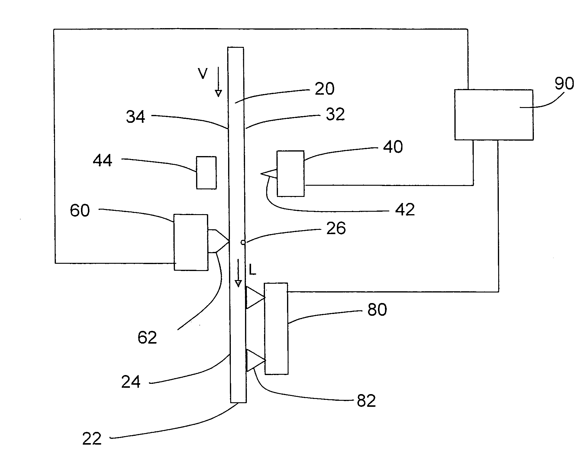
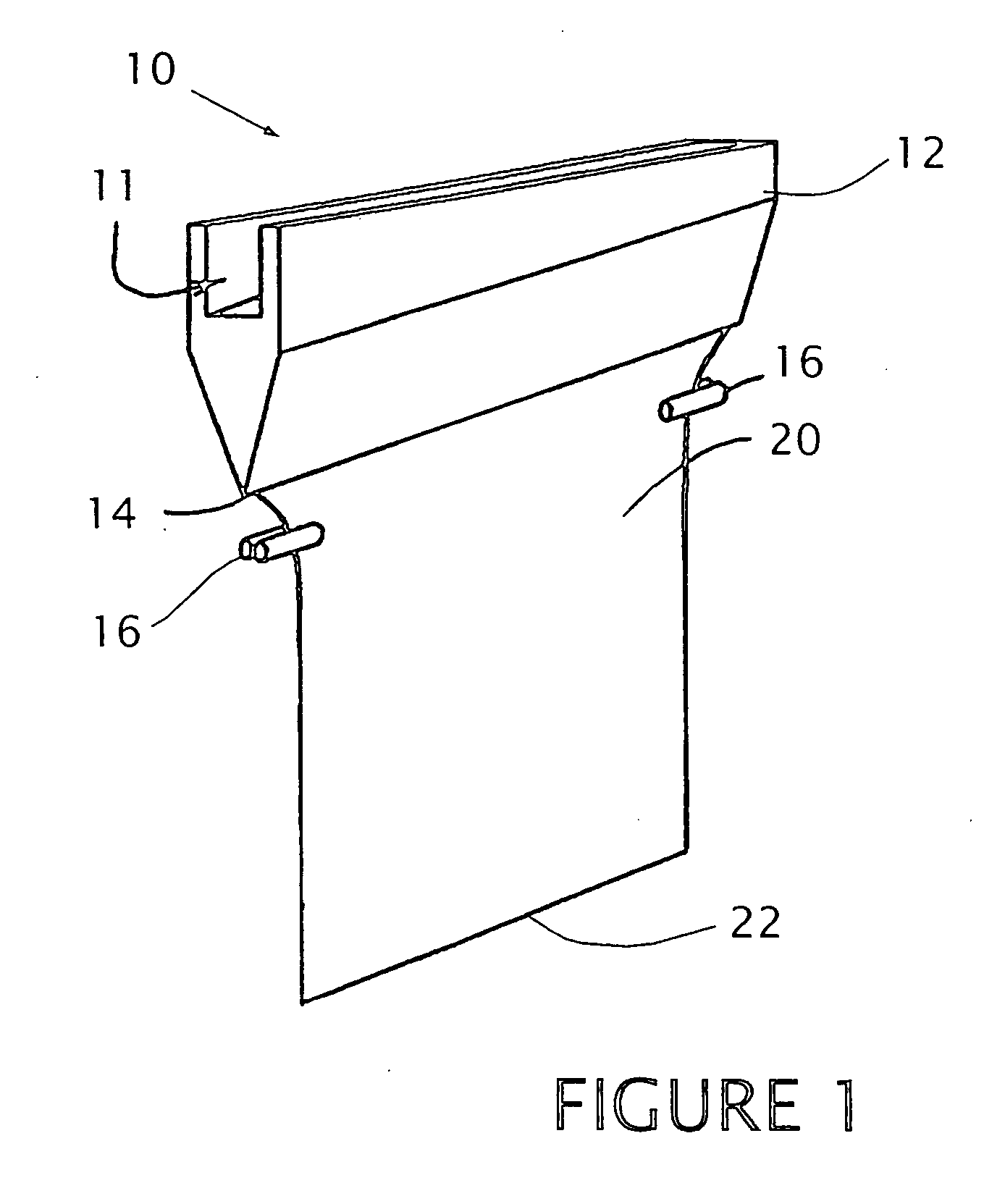
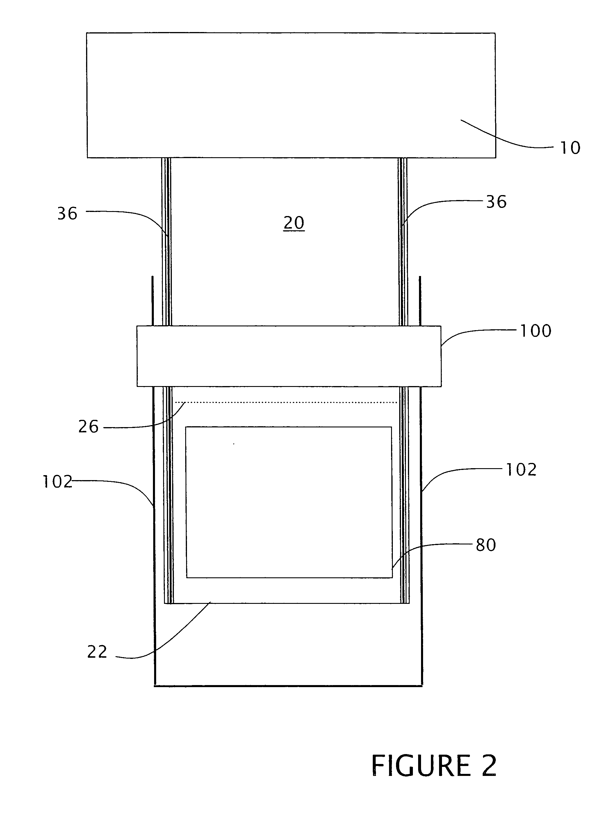
[0022] The present invention provides for the ultrasonic induced separation of a brittle material without requiring a bending or impacting of the brittle material. In one configuration, the present invention provides for the separation of a pane of a brittle material from a moving ribbon of the material, wherein selected configurations reduce the introduction of disturbances which ...


PUM

PropertyMeasurementUnit
Fractionaaaaaaaaaa
Frequencyaaaaaaaaaa
Lengthaaaaaaaaaa

Abstract

A sheet of brittle material is separated along a score line by applying ultrasonic energy to previously scored sheet material. The brittle material can be in the form of a moving ribbon, wherein a load is applied transverse to the score line to enhance crack propagation along the score line.

Description

BACKGROUND OF THE INVENTION [0001] 1. Field of the Invention [0002] The present application relates to the separation of a sheet of brittle material, and more particularly, to crack initiation and propagation along a score line in response to the application of ultrasonic energy to the brittle material. [0003] 2. Description of Related Art [0004] Two techniques are conventionally employed for cutting or shaping a sheet of brittle material, such as a glass, amorphous glass, glass-ceramic or ceramic material, to form a piece with a desired configuration or geometry. [0005] A first conventional method involves mechanical scribing of the sheet by a hard device such as a diamond or tungsten tip to score the surface of the brittle material, which is then broken along the score line in response to a bending moment applied to the material. Typically, the bending moment is applied by physically bending the brittle material about the score line. However, this process induces significant energ...

Claims


Application Information

Patent Timeline
09 Nov 2006
Publication
US20060249553A1
IPC
B26F3/00
CPC
B26D7/086; B26D7/14; B26F3/002; C03B33/033; B28D5/047; B65G2249/04; C03B33/0215; B28D5/0011
Inventors
UKRAINCZYK, LJERKA