
Segmented air floating seal

a floating seal and air technology, applied in the direction of engine seals, machines/engines, leakage prevention, etc., can solve the problems of low temperature, face seals, limited rotational speed in which they are used, etc., to achieve high temperature, low leakage (or flow), and high temperature seals

Inactive Publication Date: 2006-11-09
WILSON JACK W JR
View PDF25 Cites 20 Cited by
  • Summary
  • Abstract
  • Description
  • Claims
  • Application Information

AI Technical Summary

Benefits of technology

[0013] The object of the present invention is to provide a high temperature seal with low leakage (or flow) across the seal interface, and to provide a high temperature seal that is also durable. This objective is accomplished by providing a segmented floating seal assembly in which the seal material is made from a fiber reinforced ceramic matrix composite (FRCMC) material using fibers such as Nextel for resistance to extreme high temperatures. The annular seal is segmented in order to allow the seal to vary in circumference. When the seal surface is not rotating with respect to the seal face, the seal face is in contact with the seal surface. When the seal surface is rotating with respect to the seal face above a certain speed, the seal circumferential increases due to an air cushion formed between the face and surface producing the floating seal. The seal face is made of the FRCMC—which is a brittle material—but is mounted on a support structure like a steel plate that is very durable. The support plate carrying the FRCMC material is suspended by a metallic spring or finger extending from a main support structure to allow for the seal assembly to expand when the seal interface develops a fluid film or cushion do to the relative velocity between the face of the seal and the surface on which the seal makes contact. The face of each seal segment can include a hard face coating, since the surface of the Nextel fiber material can be somewhat rough. Any well-known hard face coating will work, but a preferable coating would be T800.

Problems solved by technology

However, a labyrinth seal does not provide a good seal in that a significant amount of fluid passes across this seal interface.
However, face seals make contact against a rotating face and thus are limited to the rotational speed in which they are used.
Also, contact seals are not used in high temperature environments.
This seal is both costly to make and not very durable in use.

Method used


Image

  • Segmented air floating seal
  • Segmented air floating seal
  • Segmented air floating seal

Examples


Embodiment Construction

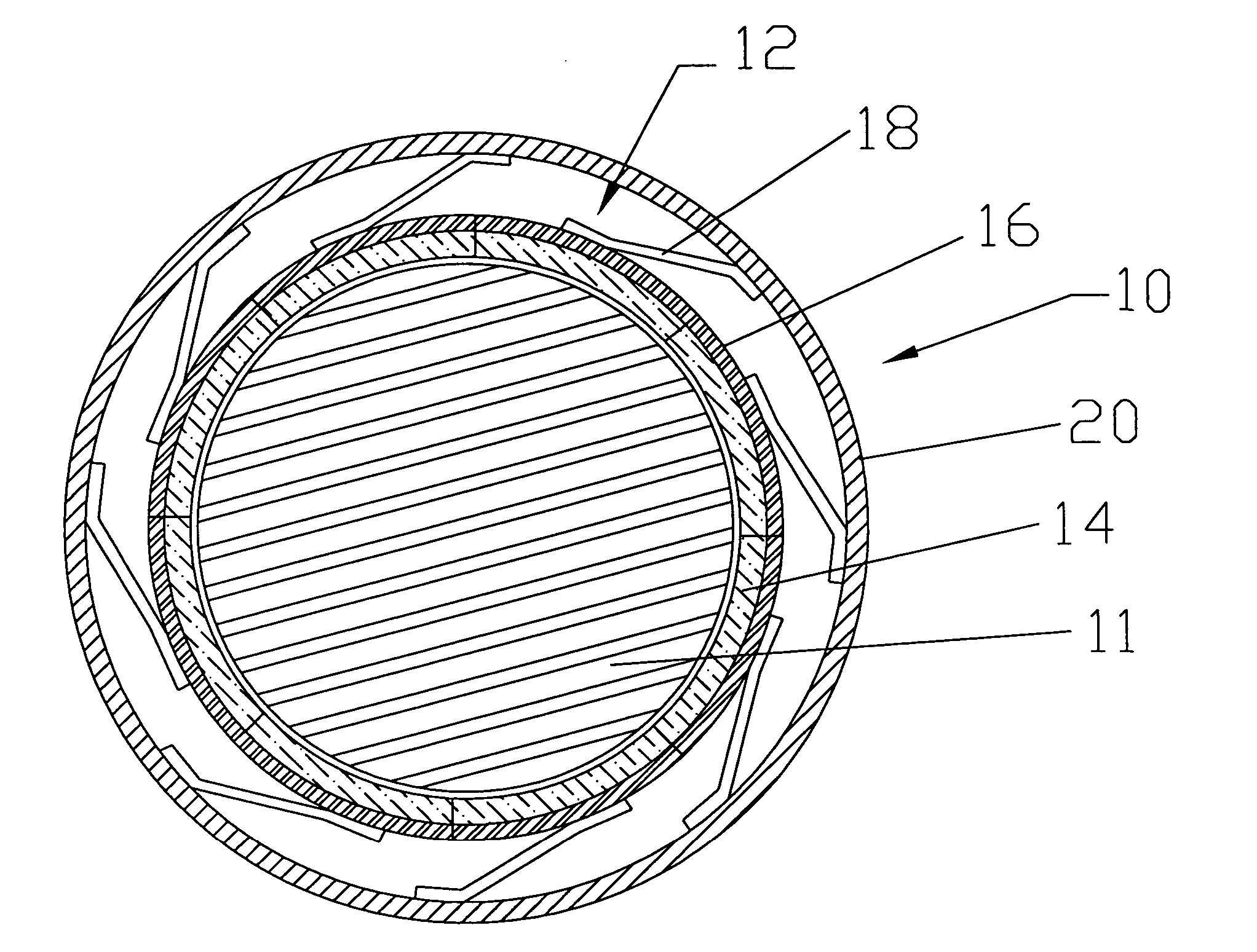
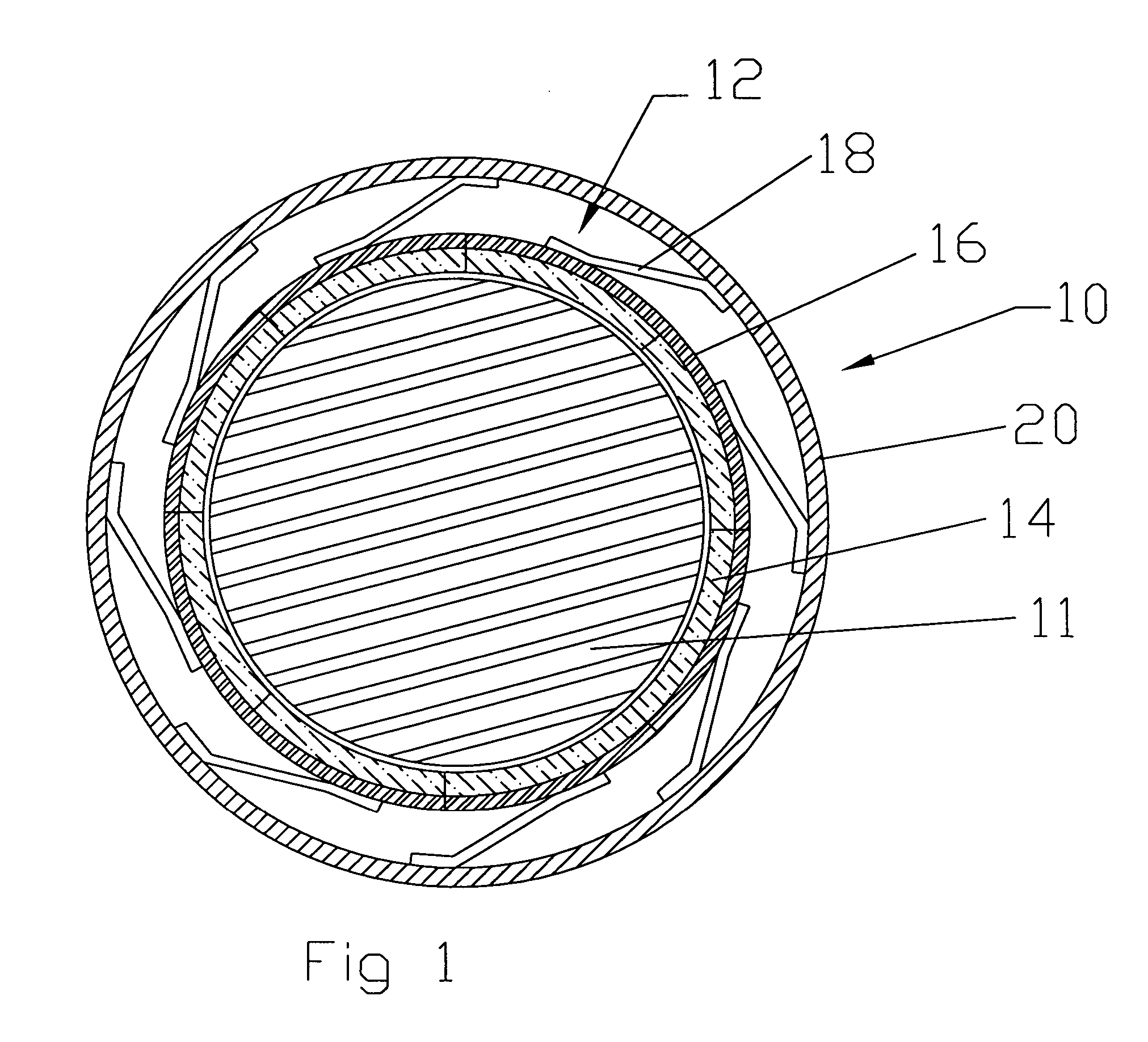
[0018] The present invention is a high temperature floating seal used in a gas turbine engine as best seen in FIG. 1. The seal assembly 10 is formed of a plurality of seal segments 12 arranged in an annular shape around a rotational shaft 11. In the FIG. 1 embodiment, there are 8 segments of equal size. Each seal segment includes a seal face 14 made from a material resistant to extremely high temperatures. In the instant invention, the seal face segments are formed of a fiber reinforced ceramic matrix composite (FRCMC) material using fibers such as Nextel. This material is described in U.S. Pat. No. 6,062,351 issued to Strasser et al, U.S. Pat. No. 5,806,636 issued to Atmur et al, U.S. Pat. No. 6,153,291 issued to Strasserand U.S. Pat. No. 6,231,793 issued to Strasser et al, each of which is incorporated herein by reference.

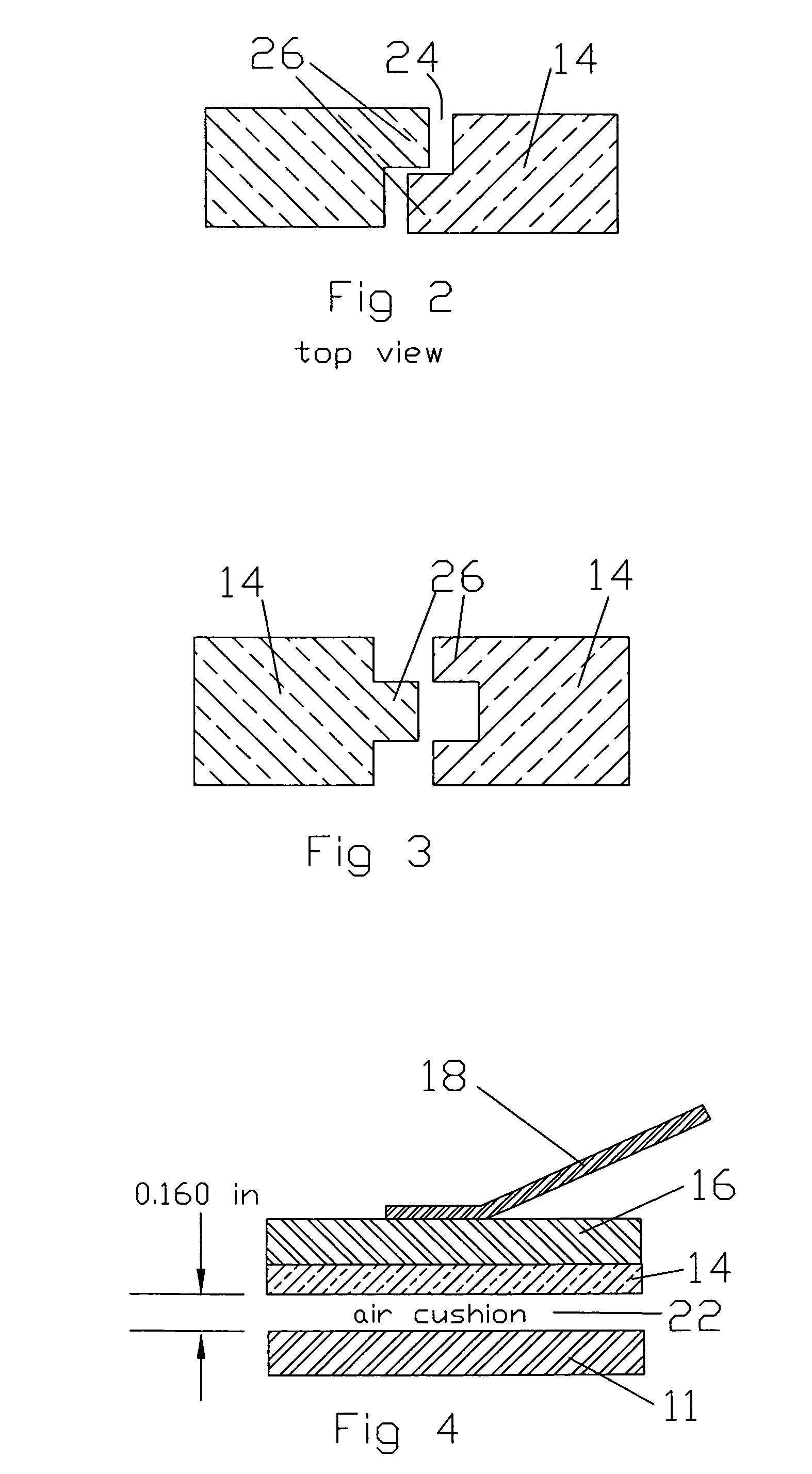
[0019] The seal face segments 14 are each secured to a metal support plate 16. The support plate provides a rigid support for the brittle ceramic material. The ...


PUM


Abstract

A segmented floating seal assembly used in a gas turbine engine to seal a rotary shaft. The segmented seal is made from a fiber reinforced ceramic matrix composite (FRCMC) material having a polymer-derived pre-ceramic resin in its ceramic state, fibers of Nextel, and a filler material. The seal segments are secured to respective support plates, and the support plates are each biased by a spring member secured to a support ring mounted in the engine. The material in the seal segments are resistive to very high temperatures, are not brittle, allow little flow across the seal face, and durable.

Description

CROSS-REFERENCE TO RELATED APPLICATION [0001] This application claims the benefit to co-pending U.S. Provisional Application No. 60 / 677,896 filed on May 5, 2005.BACKGROUND OF THE INVENTION [0002] 1. Field of the Invention [0003] The present invention relates to a floating seal in a gas turbine engine, and more specifically to a segmented, floating seal made of a heat resistant fiber reinforced ceramic matrix material such as Nextel fiber. [0004] 2. Description of the Related Prior Art including Information Disclosed under 37 CFR 1.97 and 1.98 [0005] Gas turbine engines operate under very high temperatures, temperatures that approach a melting point of the materials used in the turbine. Labyrinth seals are well known for use in high temperature environments because they can withstand these extreme temperatures. However, a labyrinth seal does not provide a good seal in that a significant amount of fluid passes across this seal interface. [0006] Contact (or, face) seals are well known ...

Claims


Application Information

Patent Timeline
IPC IPC(8): F16J15/44
CPCF16J15/442
Inventor WILSON, JACK W. JR.
Owner WILSON JACK W JR
Features
  • Generate Ideas
  • Intellectual Property
  • Life Sciences
  • Materials
  • Tech Scout
  • Unparalleled Data Quality
  • Higher Quality Content
  • 60% Fewer Hallucinations
Learn More