Exposure apparatus and device fabricating method

a technology of exposure apparatus and device, applied in the field of exposure apparatus, can solve the problems of temperature and humidity fluctuations in the environment wherein the substrate is located, the accuracy of exposure and measurement made through the projection optical system will degrade, and the insufficient focus risk of the exposure and measurement, etc., to achieve high exposure and measurement accuracy

Inactive Publication Date: 2006-11-09
NIKON CORP
View PDF22 Cites 98 Cited by
  • Summary
  • Abstract
  • Description
  • Claims
  • Application Information

AI Technical Summary

Benefits of technology

[0013] According to the present invention, the liquid that was not completely recovered by the first recovery port is recovered via the second recovery port, and it is therefore possible to prevent the outflow of the liquid. Accordingly, it is possible to prevent problems, such as: fluctuations in the environment wherein the substrate is placed due to the outflow of the liquid; as well as, for example, rusting of and electrical leakage in the members and equipment that surround the substrate and the substrate stage. In addition, although there is a possibility that vibrations will be generated when supplying and recovering the liquid, the first nozzle member, which has the supply port and the first recovery port, and the second nozzle member, which has the second recovery port, are mutually independent members, and it is therefore possible to implement optimal antivibration measures for the first and second nozzle members. Accordingly, it is possible to prevent degradation in the exposure and measurement accuracies due to vibrations generated by the nozzle members. In addition, because the first and second nozzle members are mutually independent members, work efficiency can be improved when performing maintenance on these first and second nozzle members, or when replacing them with new ones. For example, when performing maintenance on just the second nozzle member, such maintenance should be performed by removing only the second nozzle member. In so doing, it is possible to quickly implement optimal measures even if a problem arises with the first and second nozzle members. In addition, because the first and second nozzle members are mutually independent members, it is possible to increase the number of degrees of freedom in the design of the nozzle members. Accordingly, the structure of the first and second nozzle members can be simplified, and it is also possible to reduce the manufacturing cost by simplifying the manufacture of those nozzle members.
[0015] According to the present invention, the immersion area can be satisfactorily formed and high exposure and measurement accuracies can be obtained, and it is therefore possible to manufacture a device that has the desired characteristics.
[0016] According to the present invention, the operations of supplying and recovering the liquid can be satisfactorily performed, and it is therefore possible to obtain high exposure and measurement accuracies.

Problems solved by technology

If the depth of focus δ becomes excessively narrow, then it will become difficult to align the front surface of the substrate with the image plane of the projection optical system, and there will be a risk of insufficient margin of focus during the exposure operation.
For example, if vibrations are generated attendant with the operations of supplying or recovering the liquid and transmitted to the projection optical system, then a problem will arise in that the accuracy of exposures and measurements made through the projection optical system will degrade.
In addition, if a situation arises, such as the formation of an immersion area that is greater than the desired size or the inability to satisfactorily hold the liquid for forming the immersion area between the image plane side end surface of the projection optical system and the front surface of the substrate, then there is an increased possibility that the liquid in the immersion area will flow out to the outer side of the substrate or the substrate stage.
If the liquid flows out to the outer side of the substrate or the substrate stage, then there is a possibility that the vaporization of the liquid that flows out will, for example, cause (temperature and humidity) fluctuations in the environment wherein the substrate is placed.
In such a case, the thermal fluctuations of the substrate or the substrate stage, or the vaporization of the liquid will cause problems, such as wavering of the gas (air) along the optical paths of the various measurement beams that measure, for example, the positional information of the substrate, as well as degradation of the exposure accuracy, the measurement accuracy, and the like.
In addition, if the liquid flows out, then there is also a possibility that it will cause problems, such as electrical leakage as well as rusting of members and equipment in the vicinity of the substrate and the substrate stage.

Method used


Image

  • Exposure apparatus and device fabricating method
  • Exposure apparatus and device fabricating method
  • Exposure apparatus and device fabricating method

Examples


Embodiment Construction

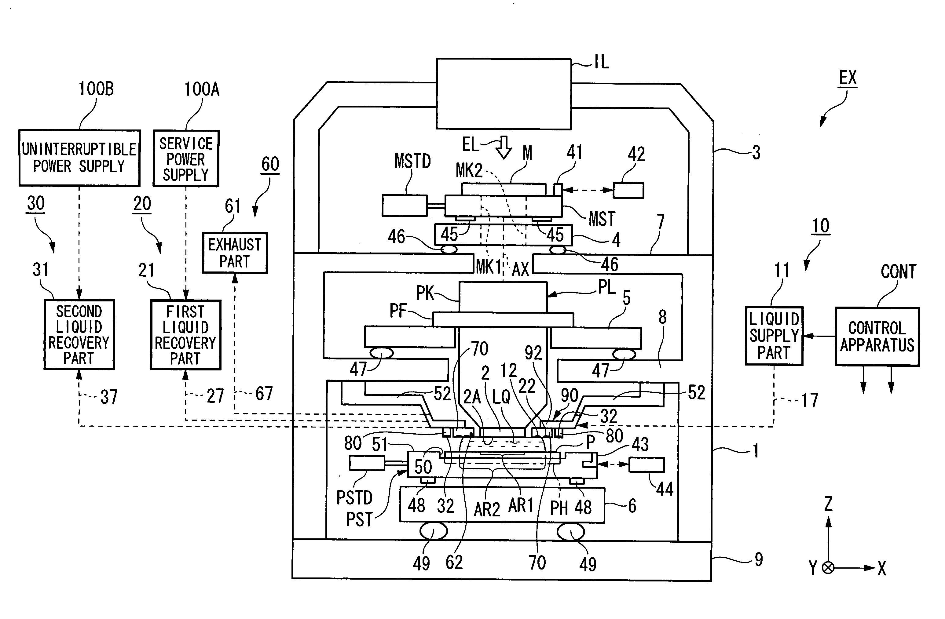
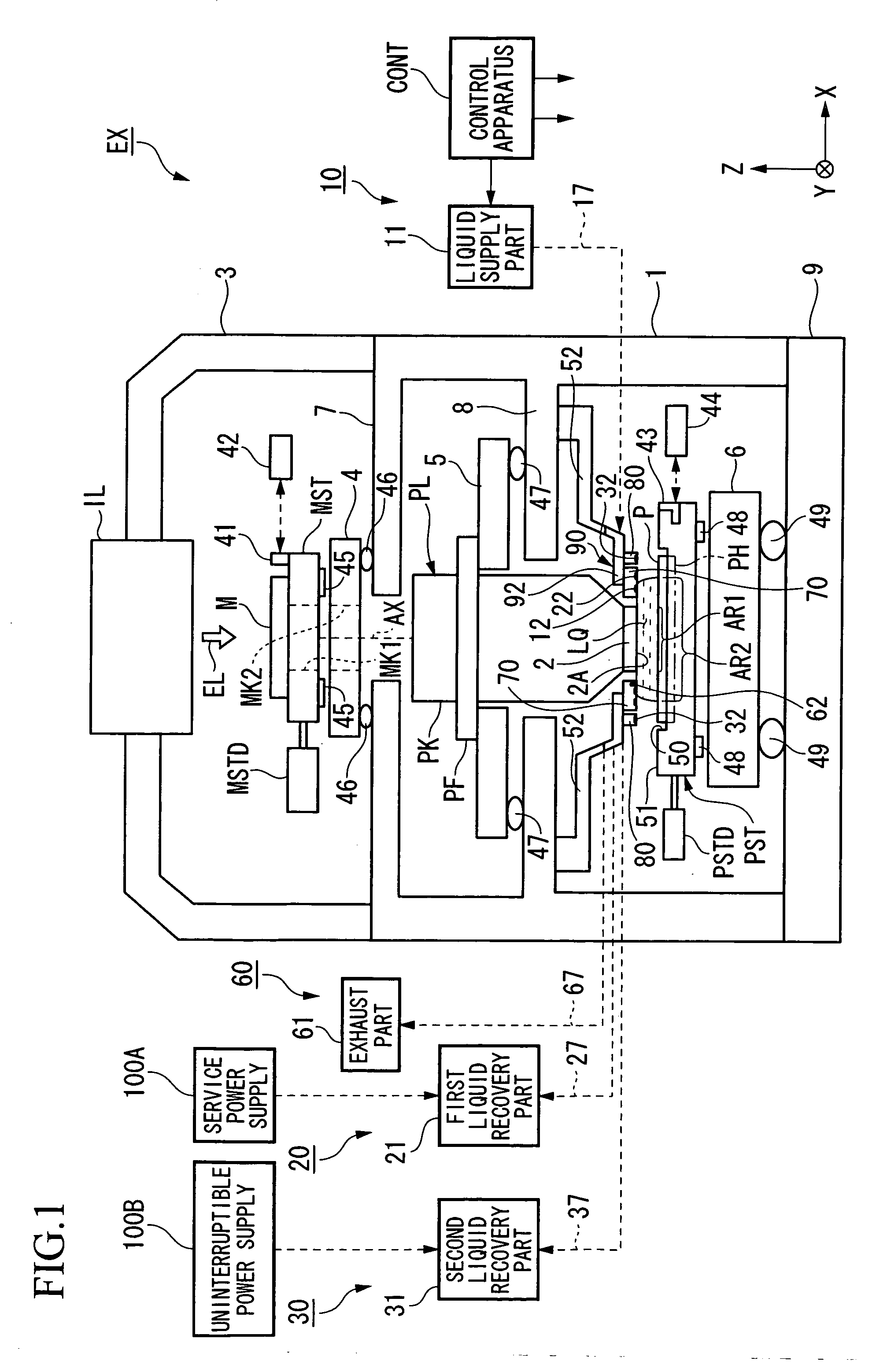
[0029] The following explains an exposure apparatus of the present invention, referencing the drawings. However, the present invention is not limited to the embodiments. FIG. 1 is a schematic block diagram that depicts one embodiment of the exposure apparatus of the present invention.

[0030] In FIG. 1, an exposure apparatus EX comprises: a mask stage MST that supports a mask M; a substrate stage PST that supports a substrate P; an illumination optical system IL that illuminates the mask M, which is supported by the mask stage MST, with an exposure light EL; a projection optical system PL that projects and exposes a pattern image of the mask M illuminated by the exposure light EL onto the substrate P that is supported by the substrate stage PST; and a control apparatus CONT that provides supervisory control of the operation of the entire exposure apparatus EX. The control apparatus CONT is connected to various measuring means (e.g., interferometers 42, 44 and a focus leveling detecti...


PUM

PropertyMeasurementUnit
wavelengthaaaaaaaaaa
refractive indexaaaaaaaaaa

Abstract

The present invention is an exposure apparatus that exposes a substrate through a projection optical system and a liquid, comprising: a first nozzle member, which is provided in the vicinity of the image plane side of the projection optical system, that has a supply port that supplies the liquid and a first recovery port that recovers the liquid; and a second nozzle member, which is provided on the outer side of the first nozzle member with respect to a projection area of the projection optical system, that has a second recovery port, which recovers the liquid, that is separate from the first recovery port. The first nozzle member and the second nozzle member are mutually independent members.

Description

BACKGROUND OF THE INVENTION [0001] 1. Field of the Invention [0002] The present invention relates to an exposure apparatus, which exposes a substrate through a projection optical system and a liquid, and a device fabricating method. [0003] 2. Description of Related Art [0004] Semiconductor devices and liquid crystal display devices are fabricated by a so-called photolithography technique, wherein a pattern formed on a mask is transferred onto a photosensitive substrate. [0005] An exposure apparatus used in this photolithographic process comprises a mask stage that supports a mask, as well as a substrate stage that supports a substrate, and transfers the pattern of the mask onto the substrate through a projection optical system while successively moving the mask stage and the substrate stage. [0006] There has been demand in recent years for higher resolution projection optical systems in order to handle the much higher levels of integration of device patterns. The shorter the exposur...

Claims


Application Information

Patent Timeline
Patent Type & Authority Applications(United States)
IPC IPC(8): G03B27/42G03F7/20H01L21/027
CPCG03F7/70341
Inventor NISHII, YASUFUMI
Owner NIKON CORP
Why Eureka
Try Eureka