
System and method for stimulation of biologic signals in a bio-electro-physiologic matrix

a bioelectrophysiologic matrix and biologic signal technology, applied in the field of implantable sensors, can solve the problems of seizure or sudden cardiac death, limited epilepsy treatment, and current technology, such as those shown in u.s. pat. nos. 6,412,490 and 5,987,352, are hampered by the use of non-biological sensing elements such as electrodes or imaging based sensing, so as to improve the specificity and sensitivity of implanted

Active Publication Date: 2006-11-09
UNIVERSITY OF ROCHESTER
View PDF6 Cites 34 Cited by
  • Summary
  • Abstract
  • Description
  • Claims
  • Application Information

AI Technical Summary

Benefits of technology

[0009] Accordingly, it is an object of the present invention to provide an implantable device for monitoring physiological changes in an organism such that the device can be operated without leads.
[0018] The specificity and sensitivity of implanted and external devices is improved by using biologic tissue itself as the signal specific sensor that is integrated into the device. The biologic cells are complex and can manage multiple inputs and outputs. In addition, the cells allow for miniaturization of the sensing device when integrated to an electronic circuit that then translates the individual cell responses to a digital signal. The cells assigned to perform the “sensor” function are integrated directly to the electronic component or within the vicinity to allow detection of the cellular matrix response.

Problems solved by technology

The treatment of epilepsy has traditionally been limited to medications or aggressive brain surgery to remove affected areas responsible for the seizures.
Both disorders are associated with an abrupt disturbance of a regular (normal) electrical rhythm resulting in chaotic electrical activation of the heart or brain which causes a seizure or sudden cardiac death.
A common thread among these technologies is their limitation to lead (wire) based technologies that rely on mechanical or electrical sensnors to determine the status of the target organ and do not specifically record non-electrical cellular activity
However, current technologies, such as those shown in U.S. Pat. Nos. 6,412,490 and 5,987,352, are hampered by the use of non-biological sensing elements such as electrodes or imaging based sensing.
Complex steps and risks are involved in obtaining venous vascular access and placement of the transvenous lead in the patient population requiring the defibrillation.

Method used


Image

  • System and method for stimulation of biologic signals in a bio-electro-physiologic matrix
  • System and method for stimulation of biologic signals in a bio-electro-physiologic matrix
  • System and method for stimulation of biologic signals in a bio-electro-physiologic matrix

Examples


Embodiment Construction

[0033] In describing a preferred embodiment of the invention illustrated in the drawings, certain specific terminology will be used for the sake of clarity. However, the invention is not intended to be limited to that specific terminology, and it is to be understood that the terminology includes all technical equivalents that operate in a similar manner to accomplish the same or similar result.

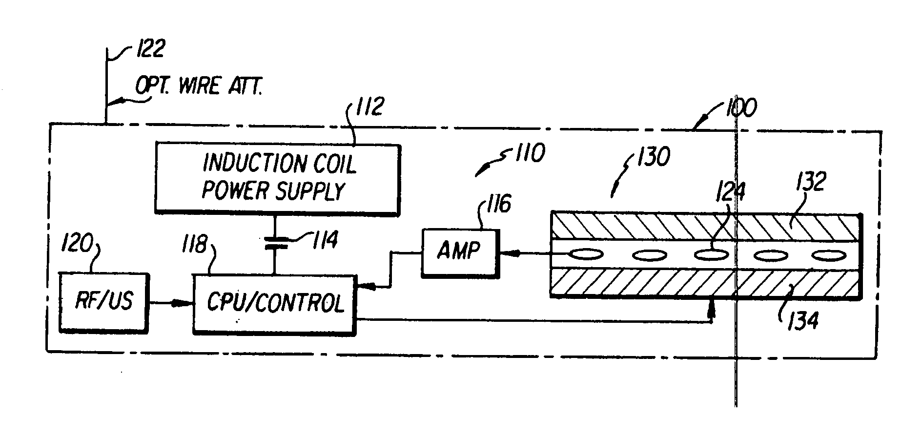
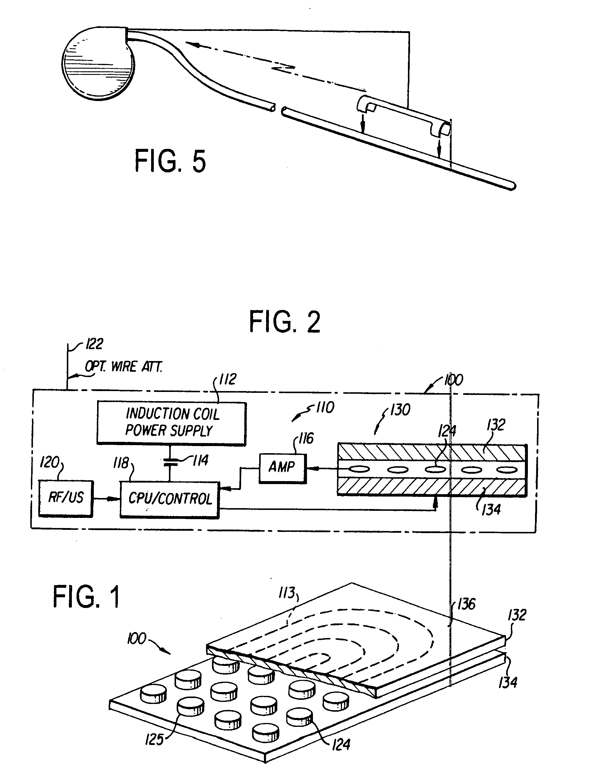
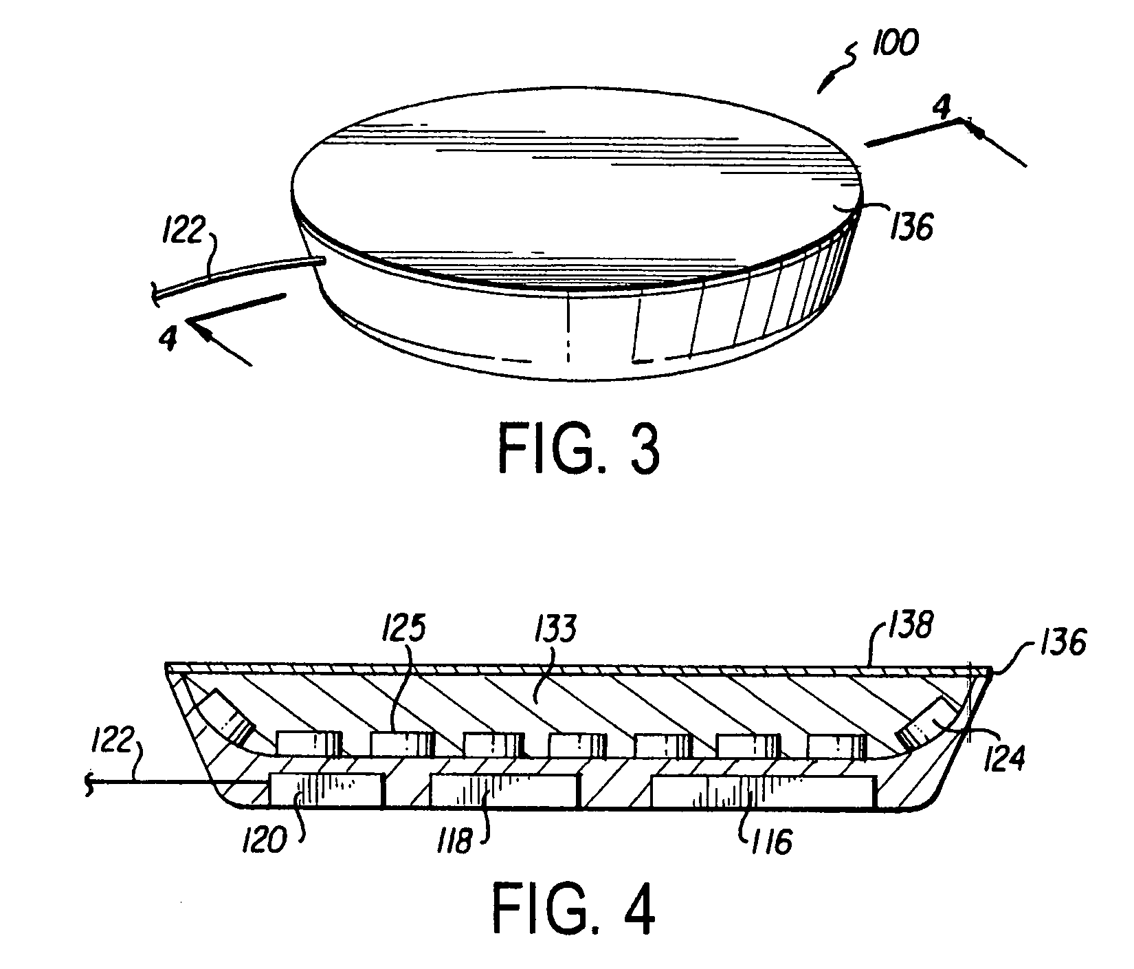
[0034] Referring to the drawings, FIGS. 1 and 2 show the bio-electro-physiologic device 100 of the present invention. The device 100 includes an electronics portion 110 and a biologic materials portion or matrix interface 130. The electronics 110 include a power supply 112, capacitor 114, amplifier 116, controller 118, communication device 120 and optional wire connector 122, and electrodes or electrode array 124. The biologic interface 130 includes two layers of cells 132, 134. However, the interface 130 can have any number of layers with various geometries, including one layer or multiple c...


PUM


Abstract

An implantable device for monitoring physiological changes in an organism is disclosed. The device includes a matrix positioned proximate a biological material of the organism, an irradiation device associated with the matrix for exposing the biological material to radiation, and a sensor device associated with the matrix for detecting a response of the biological material to the irradiation. The response can be used to remotely detect a characteristic of the biological material.

Description

CROSS-REFERENCE TO RELATED APPLICATIONS [0001] The present application is a continuation-in-part of related International Application No. PCT / US2005 / 015380.BACKGROUND OF THE INVENTION [0002] 1. Field of Invention [0003] The present invention is generally related to implantable sensors and, more particularly, to a device for facilitating two way communication and stimulation between biologic material and electronic devices. [0004] 2. Description of Prior Art [0005] The role of implantable medical devices to monitor and treat disorders of the heart, brain, nervous system and musculoskeletal system is increasingly becoming a major part of therapy and has been facilitated by recent advances in technology. Diseases that disrupt the heart, brain, or nervous system's ability to communicate or function normally include heart rhythm disorders such as ventricular fibrillation, which could be life threatening, heart block, and neurologic disorders such as epilepsy, multiple sclerosis, spinal i...

Claims


Application Information

Patent Timeline
IPC IPC(8): A61N5/02A61N1/05A61N1/372A61N1/375A61N1/39
CPCA61N1/05A61N1/362A61N1/372A61N1/3756A61N1/37288A61N1/375A61N1/37205A61N1/3629A61N1/37512A61N1/37514
Inventor ROSERO, SPENCER
Owner UNIVERSITY OF ROCHESTER
Learn More