
Dermatological treatment device with deflector optic

a treatment device and deflector technology, applied in the field of deflector optics, can solve the problems of ineffective positioning of the treatment head of the handpiece over a selected target treatment, and conventional handheld devices lack systems for preferential imaging of subsurface skin tissue, so as to facilitate image acquisition, effective diagnosis and/or treatment, the effect of facilitating image acquisition

Inactive Publication Date: 2006-11-09
PALOMAR MEDICAL TECH
View PDF99 Cites 149 Cited by
  • Summary
  • Abstract
  • Description
  • Claims
  • Application Information

AI Technical Summary

Benefits of technology

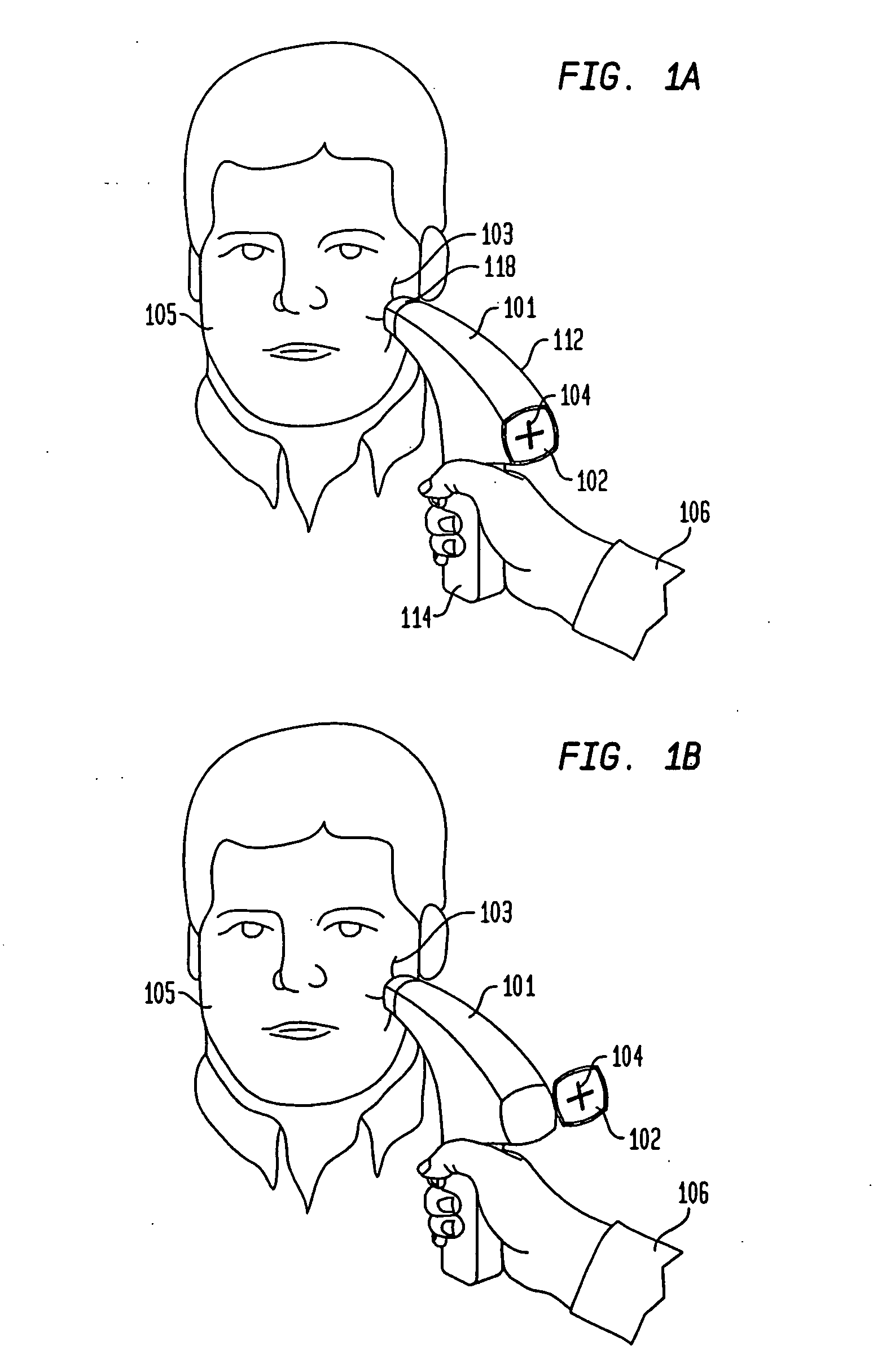
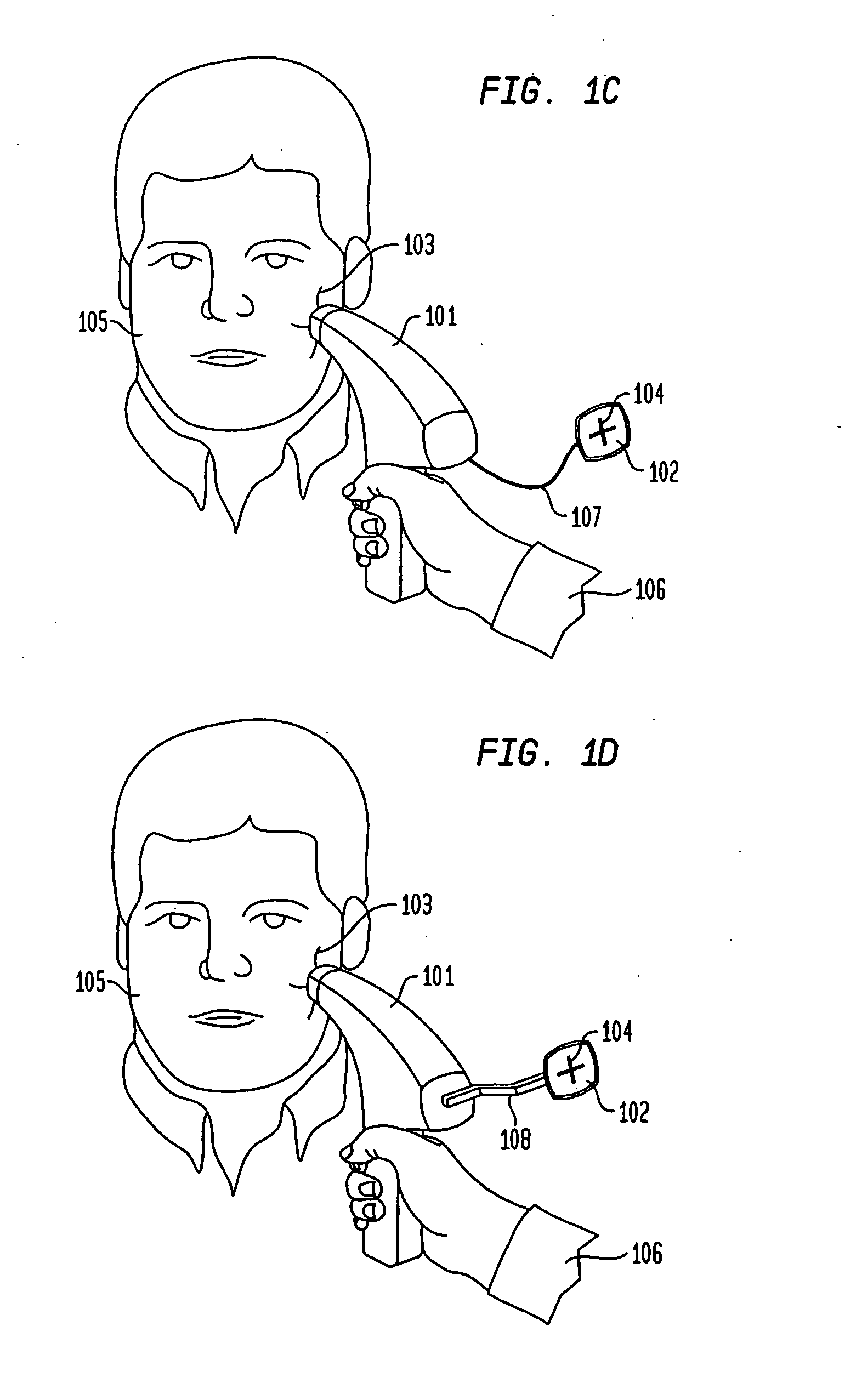
[0011] In one aspect, a handheld dermatological device is disclosed that allows application of treatment energy to a target skin region as well as visualizing the skin treatment region prior to, during, and / or after application of the treatment energy. Such a device can include, for example, an image capture device and a display device that is mounted to a housing of the handheld device and is coupled (electrically, optically or otherwise (e.g. wirelessly)) to the image capture device to present acquired images to a user, e.g., a medical professional or a consumer. The image capture device can be connected to the display through a microprocessor, which can be integrated with the display or the image capture device itself. The handheld device can further include a head that can be precisely aligned by a user relative to a patient's skin by utilizing one or more images presented in the display, and through which treatment energy can be applied to a target skin region.
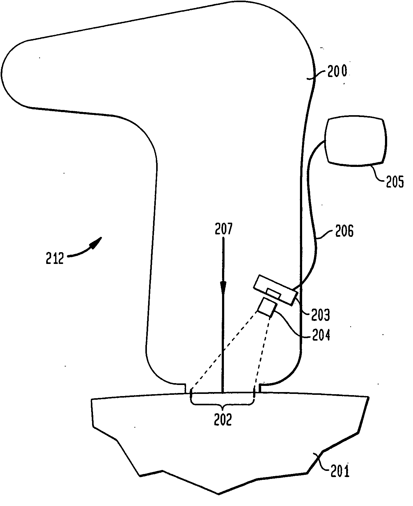
[0051] In other aspects, the invention provides a dermatological imaging device that includes a radiation guiding element (such as an optical coupling element) that is adapted to contact a skin surface region to provide refractive coupling of light into the skin (refractive illumination). The device can further include at least one illumination source that is optically coupled to the coupling element for coupling radiation into the coupling element so as to generate electromagnetic waves penetrating into a controlled depth of subsurface skin region. The device also includes an image capture device that is capable of detecting radiation scattered from the subsurface skin region in response to the refractive wave illumination. The image capture device can form an image of the subsurface skin region by employing the detected radiation. Further, in some embodiments, a filter and / or a polarizer can be coupled to the image capture device to prevent radiation having a selected polarization, or one or more selected wavelengths, from reaching the image capture device. The refractive coupling of radiation into the skin can be utilized for precise control of treatment and / or imaging of skin surface conditions and / or features, such as, stratum corneum structure, pores, sebaceous follicle openings, hair follicle openings, skin texture, wrinkles, psoriasis. By controlling the refractive index of the guiding element and the incident angle of radiation coupled into the coupling element at the contact surface of the coupling element and the skin, the imaging contrast of a visualized target can be enhanced, as discussed in more detail below.

Problems solved by technology

While various handheld devices have been disclosed for applying dermatological treatments, currently, present systems lack efficient mechanisms for positioning the treatment head of the handpiece over a selected target treatment area and / or viewing the target area while a treatment modality is being applied.
Further, such conventional handheld devices lack systems for preferential imaging of subsurface skin tissue.

Method used


Image

  • Dermatological treatment device with deflector optic
  • Dermatological treatment device with deflector optic
  • Dermatological treatment device with deflector optic

Examples


Embodiment Construction

[0097] The present invention relates generally to dermatological devices, and more particularly to handheld dermatological devices for applying a variety of treatment modalities to a patient's skin or any other tissue while allowing a user to view the treatment area and target before, during, and after application of the treatment. In some embodiments, the handheld device can include one or more radiation sources for illuminating a target region of the patient's skin so as to facilitate imaging that region by an image capture device, and can further include a display in which an image of the target region can be presented.

[0098]FIG. 1A schematically depicts a handpiece device 112 according to one embodiment of the invention having a housing 101 that includes a handle 114 that allows a user 106, e.g., a medical professional, a home user, or a beautician to hold and aim the device at a selected target treatment area 103. The housing 101, which defines an enclosure in which various co...


PUM


Abstract

This invention relates generally to methods and apparatus for utilizing energy, e.g., optical radiation, to treat various dermatological and cosmetic conditions. A handheld dermatological device that facilitates viewing and measuring parameters of a treatment area before, during, and after application of a treatment modality, and methods of use therefor, are disclosed. The device can include a deflective device that can steer radiation to control a target position of the radiation. The device can also include a control device to allow a user to control the radiation through manipulation of the deflective device.

Description

RELATED APPLICATIONS [0001] This application claims benefit of priority to U.S. Provisional Application No. 60 / 654,123, filed Feb. 18, 2005, the entire disclosure of which is incorporated herein by reference.TECHNICAL FIELD [0002] This invention relates generally to methods and apparatus for utilizing energy, e.g. optical radiation, to treat various dermatological and cosmetic conditions. BACKGROUND OF THE INVENTION [0003] Energy such as electromagnetic, mechanical, thermal, acoustic, and particle beam radiation has been utilized for many years in medical and non-medical facilities to treat various medical and cosmetic conditions. Such treatments include, but are not limited to, hair growth management, including limiting or eliminating hair growth in undesired areas and stimulating hair growth in desired areas, treatments for PFB (razor bumps), skin rejuvenation, anti-aging treatments including improving skin texture, elasticity, wrinkles and skin lifting and tightening, pore size r...

Claims


Application Information

Patent Timeline
Patent Type & Authority Applications(United States)
IPC IPC(8): A61N5/06
CPCA61B18/20A61B18/203A61B19/52A61N2005/0629A61B2018/00904A61B2018/2095A61B2018/00452A61B90/36A61B2018/20359
Inventor CARUSO, JOSEPH P.ALTSHULER, GREGORY B.O'SHEA, LIAM
Owner PALOMAR MEDICAL TECH
Learn More