System for the controlled delivery of stents and grafts

a graft and controlled technology, applied in the field of percutaneous transluminal vascular procedures, can solve problems such as rendering the graft leak-proo

Inactive Publication Date: 2006-11-09
AMPLATZ KURT
View PDF74 Cites 105 Cited by
  • Summary
  • Abstract
  • Description
  • Claims
  • Application Information

AI Technical Summary

Benefits of technology

[0013] The stent, stent graft or graft deployed using the apparatus of the present invention comprises a large plurality of very fine braided metal strands exhibiting a memory property and which is radially collapsible to a relatively small size for passage through the outer tubular guide catheter but which, when released from the guide catheter, self-expands to a relatively large diameter. The number of strands, the diameter of each strand, the pitch and pick of the braid are such that the pore size of the resulting tubular graft is sufficiently small that fibrin present in the blood will close such pores, rendering the graft leak-proof. The braided tubular graft is installed on the delivery system by capturing the free ends of the strands comprising the braided graft at its proximal end between the bead member affixed to the elongate flexible member and the wall defining the lumen of the inner tubular pusher catheter at its distal end. The compression spring is used to maintain the requisite tension force on the elongate member to maintain the ends of the strands pinched between the bead member and the wall of the inner tubular pusher catheter proximate its distal end.

Problems solved by technology

The number of strands, the diameter of each strand, the pitch and pick of the braid are such that the pore size of the resulting tubular graft is sufficiently small that fibrin present in the blood will close such pores, rendering the graft leak-proof.

Method used


Image

  • System for the controlled delivery of stents and grafts
  • System for the controlled delivery of stents and grafts

Examples


Embodiment Construction

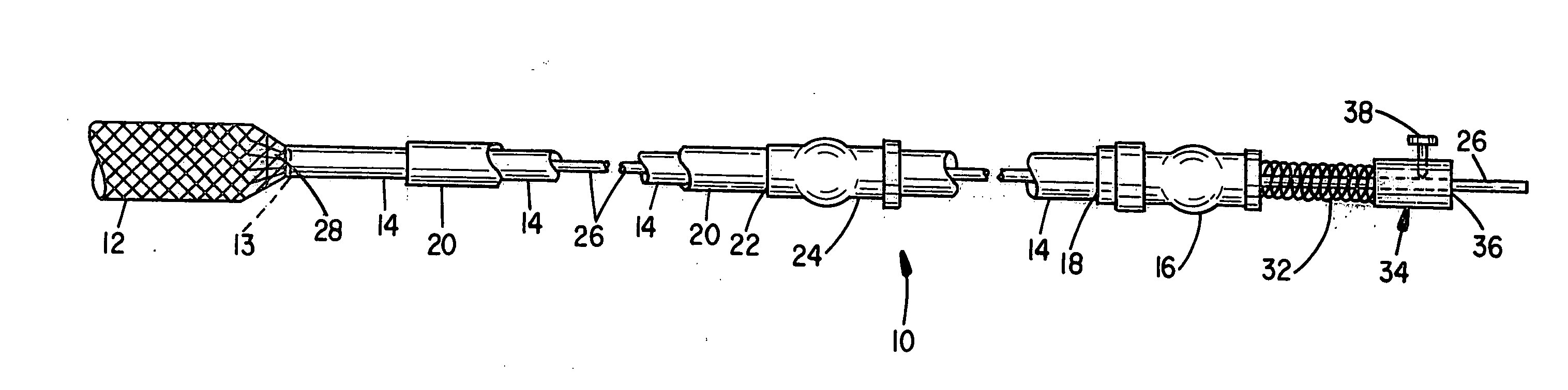
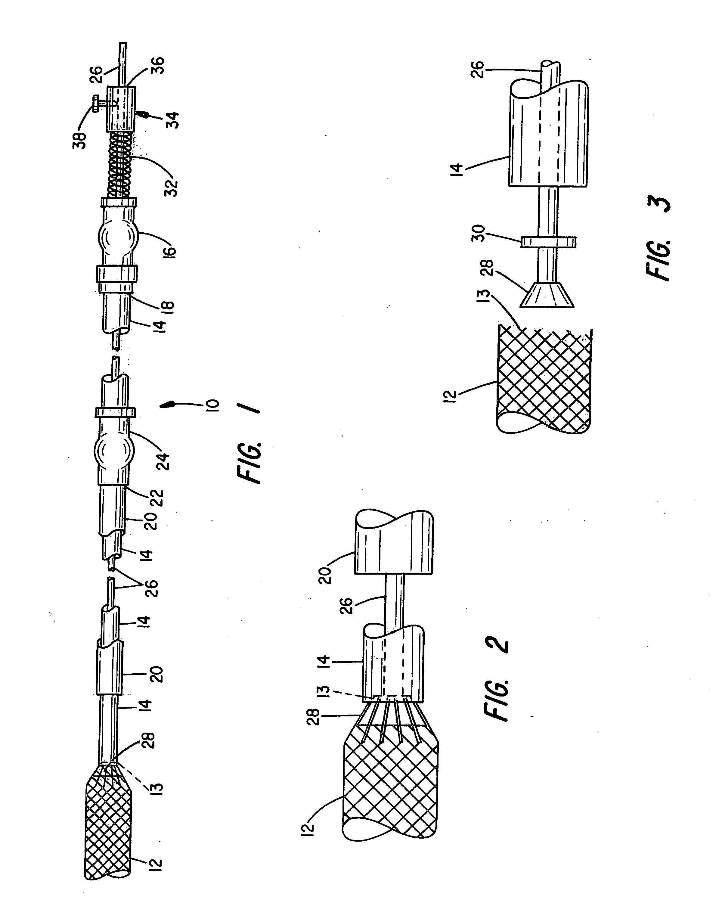
[0018] Referring first to FIG. 1, the percutaneous translumenal stent or graft delivery system is identified generally by numeral 10 and, as already indicated, is used to deliver a stent or graft member 12 to a target site within the vascular system such as at the location of an abdominal aortic aneurysm for the purpose of exclusion of the aneurysm to prevent further bulging and possible rupture thereof.

[0019] The vascular prosthesis 12 is preferably formed of a metal fabric exhibiting an expanded configuration and a collapsed configuration. The prosthesis, when collapsed, can be deployed through the lumen of a catheter and, upon exiting the distal end of the catheter at a target site in a patient's vascular system, will substantially return to its expanded configuration.

[0020] As is described in U.S. Pat. No. 5,725,552 to Curtis Amplatz, the metal fabric comprising the prosthesis may comprise a plurality of braided metal strands where the metal is preferably a shape memory alloy ...


PUM


Abstract

The present invention provides a delivery mechanism for percutaneously routing a stent or graft through the vascular system and procedures for addressing an aneurysm or an otherwise damaged vessel. The delivery system includes an outer tubular guide catheter 20, an inner tubular delivery (pusher) catheter 14 coaxially disposed and slidable relative to the outer guide catheter and an elongated flexible wire or cable 26 that is coaxially insertable through the lumen of the inner tubular catheter and that has a frusto-conical bead affixed at the distal end thereof which is sized to at least partially fit within the lumen of the inner pusher catheter when a proximally directed tension force is applied between the elongated flexible wire or cable 26 with respect to the pusher catheter 14. By inserting a compressed coil spring between a proximal end portion of the pusher catheter 14 and the proximal end portion of the cable 26, the requisite clamping force is maintained to secure the stent or graft to the distal end of the pusher catheter until the compression spring force is removed. With the stent or graft clamped to the distal end of the inner pusher catheter, it can be drawn within the lumen of the outer guide catheter for delivery therewith to the target site.

Description

BACKGROUND OF THE INVENTION [0001] II. Field of the Invention [0002] This invention relates generally to percutaneous transluminal vascular procedures and more particularly to delivery apparatus for placing a stent, a stent graft or a tubular graft at a desired target location within a subject's vascular system. [0003] II. Discussion of the Prior Art [0004] In the field of interventional cardiology, it is now becoming routine to treat stenotic lesions in the vascular system using balloon angioplasty to render more patent a partially occluded blood vessel and to attempt to thwart restenosis by placement of a stent at the site of the treated lesion. [0005] Stents used in these procedures must be capable of assuming a reduced diameter configuration for delivery through a guide catheter, but which are either self-expanding upon exit of the distal end of the guide catheter or “balloon expandable”. [0006] In carrying out a balloon angioplasty procedure with stenting, the Seldinger techniq...

Claims


Application Information

Patent Timeline
Patent Type & Authority Applications(United States)
IPC IPC(8): A61F2/06
CPCA61F2/95
Inventor AMPLATZ, KURT
Owner AMPLATZ KURT
Why Eureka
Try Eureka