Television receiver and external devices

a receiver and receiver technology, applied in the field of television receivers and external devices, can solve the problems of dvhs operation menu, difficult to transmit osd (on screen display) data, and inability to automatically recognize an external device connected through the analog video signal input terminal

Inactive Publication Date: 2006-11-16
PANASONIC CORP
View PDF4 Cites 64 Cited by
  • Summary
  • Abstract
  • Description
  • Claims
  • Application Information

AI Technical Summary

Benefits of technology

[0027] Therefore, a sync signal detection circuit which has conventionally been required is dispensed with, whereby the circuit structure is simplified. Further, analog connection setting can be automatically carried out in a short time even when the external devices are daisy-chained, whereby user operability is enhanced.
[0056] Therefore, it is possible to provide a playback system which can automatically perform analog connection setting by a simple circuit structure.

Problems solved by technology

Although the IEEE1394 line can perform packet transmission of video and audio compressed streams, it is difficult to transmit OSD (On Screen Display) data, such as a DVHS operation menu, as a compressed stream through the IEEE13984.
Although the TV side can automatically recognize an external device connected to the TV through the IEEE1394 line when the external device is connected by the IEEE1394 line, it cannot automatically recognize an external device connected through the analog video signal input terminal.
In the conventional construction, however, when the user performs analog connection setting on the OSD screen, it is a very bothersome operation for the user to successively switch and select the items using operation buttons on a remote controller or the like, as shown in FIG. 15(c).
Further, since the user himself must perform such setting while checking the connection status of cables on a back panel as shown in FIG. 14, the user is apt to be confused, leading to possibility of mistake.
In order to perform the above-mentioned analog connection setting, however, a sync signal detection circuit is required on the TV side, which leads to an increase in circuit scale and cost.
Further, the above-mentioned analog connection setting takes a certain amount of time from setting start to end.
Therefore, it takes time from the reception of the power-on instruction to the outputting of the sync signals.
As a result, the time for the analog connection setting is undesirably increased, and the user should wait in the meantime.
Further, in the above-mentioned analog connection setting, since discrimination of analog connection terminals is carried out by detecting the sync signals, when plural external devices are connected, it is impossible to simultaneously perform analog connection settings for all the plural external devices.
Furthermore, in the technique described in the above-mentioned literature, when the external devices are connected by digital lines such as HDMI (High Definition Multimedia Interface) lines and IEEE1394 lines, since there is no sync signal in digital data outputted from the external devices, a special circuit for detecting a pattern of sync signals is required, whereby the whole circuit scale is increased, leading to cost increase.
Further, digital lines such as HDMI lines cannot be automatically recognized in contrast to the IEEE1394 lines, it is necessary to perform digital setting for making the TV side recognize as to which digital lines are connected to which external devices, resulting in an increase in setting time.

Method used


Image

  • Television receiver and external devices
  • Television receiver and external devices
  • Television receiver and external devices

Examples


embodiment 1

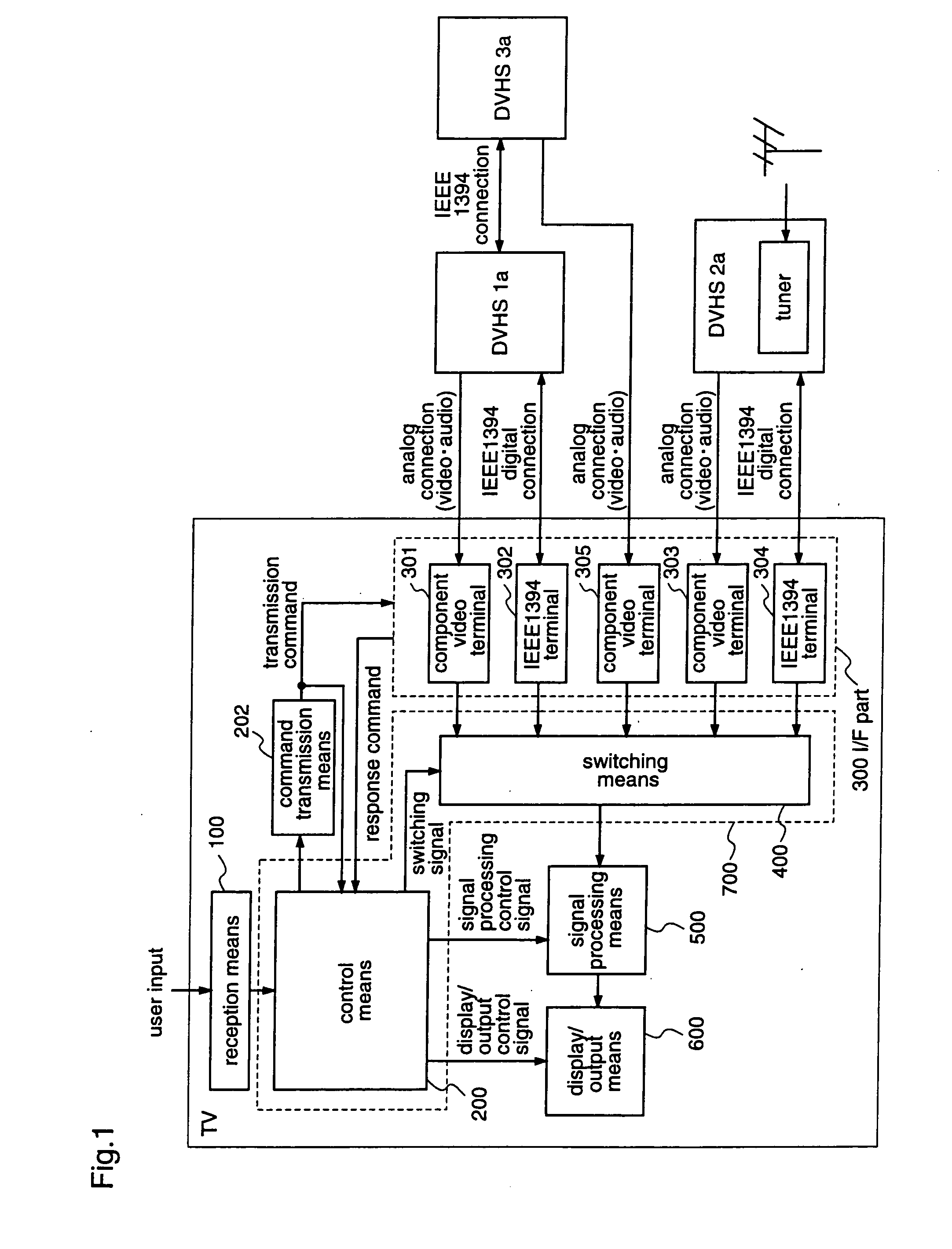
[0075]FIG. 1 is a diagram illustrating a schematic construction of a television receiver according to a first embodiment of the present invention.

[0076] The television receiver (TV) comprises a reception means 100, an I / F part 300, a signal processing means 500, a display / output means 600, a command transmission means 202, and a switching control means 700.

[0077] The reception means 100 receives an instruction from a user.

[0078] The I / F part 300 exchanges data with an external device. This I / F part 300 has component video terminals 301, 303, and 305 as analog video signal input terminals, and IEEE1394 terminals 302 and 304. In this first embodiment, DVHS 1a, DVHS 2a, and DVHS 3a are analog-connected to the component video terminals 301, 303, and 305, respectively. Further, DVHS 1a and DVHS 2a are digital-connected to the IEEE1394 terminals 302 and 304, respectively. The DVHS 2a houses a tuner which enables the DVHS 2a to receive broadcast waves. The DVHS 3a is daisy-chained with ...

embodiment 2

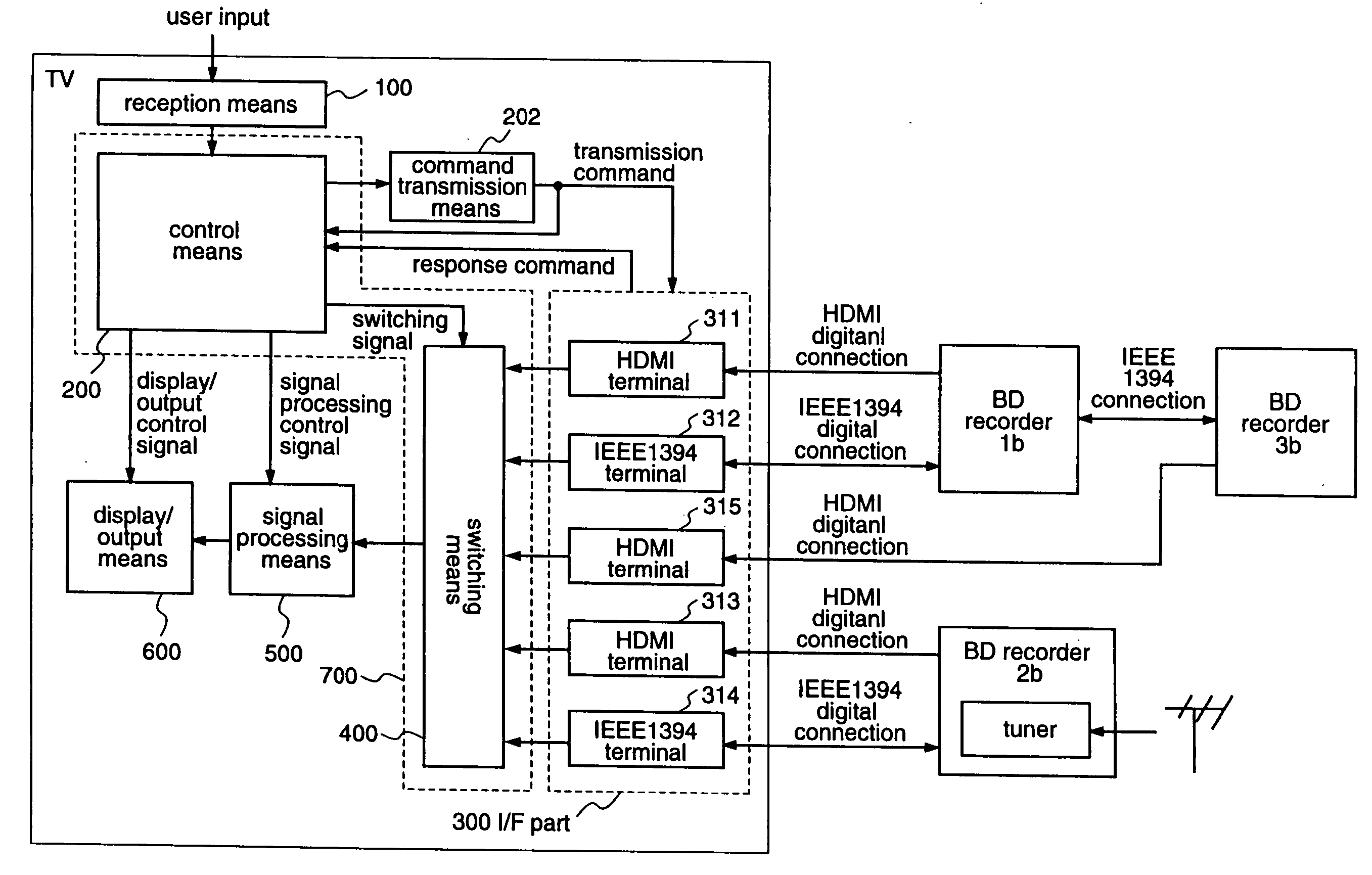
[0097]FIG. 4 is a diagram illustrating the construction of a television receiver according to a second embodiment of the present invention. In FIG. 4, the same reference numerals as those shown in FIG. 1 denote the same elements.

[0098] This second embodiment is different from the first embodiment in that the television receiver of the second embodiment includes plural IEEE 1394 terminals and plural HDMI terminals while the television receiver of the first embodiment includes plural IEEE1394 terminals and plural analog input terminals.

[0099] The I / F part 300 includes HDMI terminals 311, 313, and 315 as digital input terminals, and IEEE1394 terminals312 and 314 as digital terminals.

[0100] In this second embodiment, it is assumed that blue-ray disc recorders (BD recorders) 1b, 2b, and 3b are connected as external devices. The BD recorder 3b is daisy-chained with the BD recorder 1b by an IEEE1394 line, whereby the BD recorder 3b can exchange data with both of the BD recorder 1b and t...


PUM


Abstract

A television receiver according to the present invention successively transmits the same transmission command to external devices (1a)˜(3b) connected through IEEE (1394) lines and HDMI lines, and monitors the DC levels of HDMI terminals to which the respective HDMI lines are connected, thereby to discriminate the HDMI lines used for transmission of response commands that are outputted from the respective BD recorders (1b)˜(3b) in response to the transmission commands, and then automatically performs switching between the IEEE (1394) lines and the HDMI lines which are used by the respective BD recorders (1b)˜(3b), according to the operations of the BD recorders (1b)˜(3b). Therefore, with respect to the plural external devices which are connected to the television receiver through the HDMI lines and the IEEE (1394) lines, it is possible to automatically recognize as to which external devices are connected to which HDMI lines, whereby bothersome settings as those required in the conventional device are dispensed with, leading to enhanced user operability.

Description

TECHNICAL FIELD [0001] The present invention relates to a television receiver, and external devices which are connected to the television receiver through IEEE1394 lines. BACKGROUND ART [0002] In recent years, with a spread of digital broadcasting, digitization of AV equipment such as televisions and VTRs have been progressed, and those equipment utilizing AV network standard such as IEEE1394 have increased. The IEEE1394 is a digital interface that can mutually connect digital AV devices, and the IEEE1394 enables the AV devices to constitute a network and exchange AV streams with each other. [0003] A schematic construction of a television receiver (TV) including such IEEE1394 is shown in FIG. 11. [0004] The TV shown in FIG. 11 comprises a receiving means 10 for receiving information inputted by a user, a control means for controlling function blocks according to the input information, an I / F part 30 for performing data exchange with an external device, a switching means 40 for chang...

Claims


Application Information

Patent Timeline
Patent Type & Authority Applications(United States)
IPC IPC(8): H04N7/00H04L12/40H04L12/64H04N5/44H04N5/775H04N7/173
CPCH04L12/40117H04N5/4401H04N5/775H04N21/43635H04N21/43622H04N21/43632H04N21/4135H04N21/426H04L12/64H04N5/44
Inventor SUZUKI, HIDEKAZUOYAMA, TETSUOYAMADA, MASAZUMI
Owner PANASONIC CORP
Why Eureka
Try Eureka