
Method and apparatus for the continuous performance monitoring of a lead acid battery system

a lead acid battery and continuous performance technology, applied in secondary cell testing, cell structure combination, instruments, etc., can solve the problems of considerable monetary loss, considerable service loss, and inconvenience, and achieve the effect of reducing manipulation and facilitating installation

Inactive Publication Date: 2006-11-16
ZACCARIA ROBERT
View PDF35 Cites 37 Cited by
  • Summary
  • Abstract
  • Description
  • Claims
  • Application Information

AI Technical Summary

Benefits of technology

[0011] It is an object of the invention to provide an interface device which provides adequate information between at least a portion of a string of batteries serially connected and which can be easily installed with a minimum of manipulation.
[0014] It is another object of the invention to provide a battery monitoring system which accurately and easily measures the battery impedance for each battery in a string of batteries. A corollary object of the invention is to provide a method for measuring the battery impedance of a plurality of batteries serially connected to form at least one string of batteries.

Problems solved by technology

However, battery systems represent what has been termed a bullet approach, i.e. their performance is only truly evaluated when they are in use.
This is a considerable inconvenience, since the reliability of the entire system is dependent on each of the batteries.
Should the battery system fail, this can lead to considerable monetary loss, and considerable loss of service with critical consequences, particularly in the case of hospital equipment and telecommunications systems.
Some of these symptoms can lead to entire system failure and the requirement for premature (and costly) replacement.
One condition in particular can create a dangerous situation for persons servicing the system or bystanders: thermal runaway.
Thermal runaway is a critical condition arising during constant voltage charging in which the current and the internal temperature of a battery produce a cumulative mutually reinforcing effect which further increases them and can lead to the destruction of the battery.
However, the present systems represent a relatively complex installation process and do not, according to the Applicant, provide continuous performance monitoring.
However, each of these systems describes a complex installation process, and the installation of some of these systems may require taking the battery system off-line during set-up which users do not appreciate.
The disadvantage with this system is that it is cumbersome to install, and the voltage that is measured is done so for the totality of the half-string, not for each individual battery and so is the resulting value for the impedance.

Method used


Image

  • Method and apparatus for the continuous performance monitoring of a lead acid battery system
  • Method and apparatus for the continuous performance monitoring of a lead acid battery system
  • Method and apparatus for the continuous performance monitoring of a lead acid battery system

Examples


Embodiment Construction

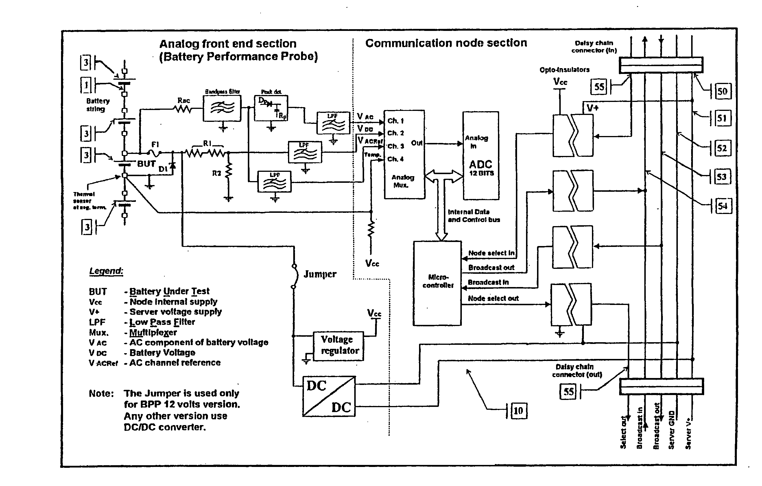
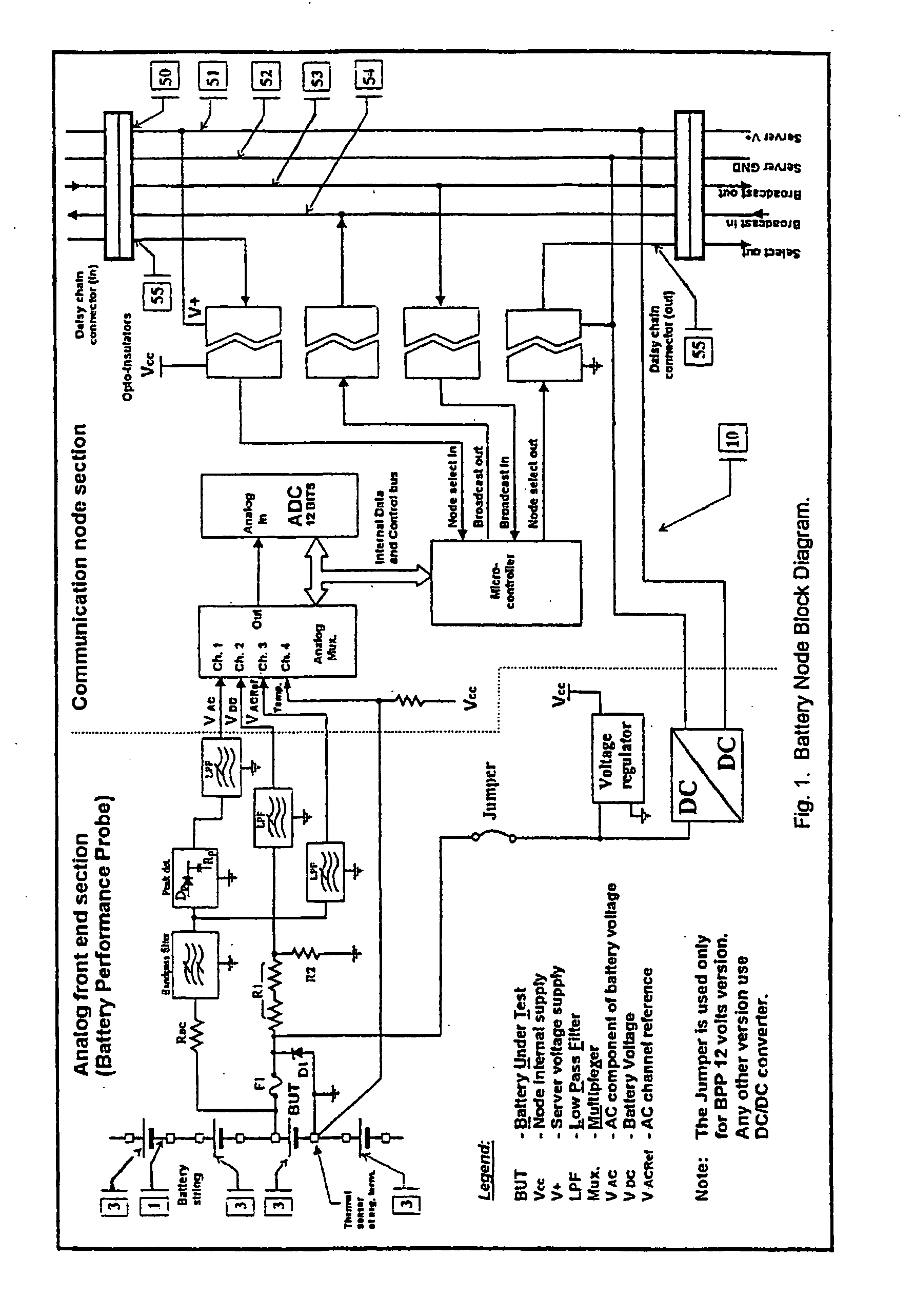
[0029] Traditional back-up battery systems comprise a plurality of batteries 3 connected in series to form a string 1. A back-up system can include more than one string 1 (although only one is shown in FIG. 1), depending on the power requirements of the user. Such an arrangement is well known in the prior art.

[0030] A battery monitoring system according to the present invention basically comprises a number of interface devices including probe means 10 and bus means 50 (shown in FIG. 1) and a system server 100. The probe means 10 are individually connected to a corresponding portion of a string 1 of batteries 3, and are serially interconnected to the bus means 50, which in the preferred embodiment of the invention is a daisy chain bus having five wires, two of which are used for power 51, 52, one is a broadcast out 53, one is a broadcast in 54 and one is a select 55. It should be noted that only the select 55 wire performs the serial interconnection (as shown in FIG. 1), and the oth...


PUM

PropertyMeasurementUnit
Zener voltageaaaaaaaaaa
voltageaaaaaaaaaa
voltageaaaaaaaaaa

Abstract

The present invention concerns a battery monitoring system for monitoring a plurality of batteries serially connected to form a string. The battery monitoring system includes a number of probes connected to at least a portion of the string, a daisy chain bus having a select channel for serially interconnecting the probes, the bus having other, parallel channels for data communication and power, and a system server. The probes each have a sensing module and a communication module. The sensing module senses characteristics of at least a portion of the string, such as voltage or current. The communication module receives the sensed characteristics and converts them into digital form for broadcast to the system server over the bus. The communication module of the probes have a memory for storing an address assigned to the corresponding probe upon reception of an initialization signal sent by the system server via the bus. In order to readdress all of the probes, a reset signal is transmitted to all of the probes. The probes clear the present address, and wait until they are selected through the select channel. Once the probe has been selected, it receives an address from the system server, stores the address in its memory, acknowledges this to the system controller, and sends a signal on the select channel to the next probe. Accordingly, initialization of a battery monitoring system is easily performed. The invention also lies in an interface device for use with a battery monitoring system.

Description

FIELD OF THE INVENTION [0001] The present invention relates to a method and apparatus for the continuous performance monitoring of a lead acid battery system, and more particularly to such a method and apparatus which is easier to install and implement and provides added flexibility. DESCRIPTION OF THE PRIOR ART [0002] Lead acid batteries are a commonly used source of electrical energy in the case when a main source, typically an AC supply line, fails. Typically, a bank of batteries will be interconnected in a system configuration to provide the desired voltage and power for short term emergency situations, until the AC supply line is re-established or until a generator can provide the necessary power requirements. Such systems are often used as back-ups for hospital equipment, telecommunications equipment, computer equipment, etc. [0003] However, battery systems represent what has been termed a bullet approach, i.e. their performance is only truly evaluated when they are in use. Th...

Claims


Application Information

Patent Timeline
Patent Type & Authority Applications(United States)
IPC IPC(8): G06F11/00G01R31/36G08B21/00H01M10/42H01M10/46H01M10/48H02J9/00H02J13/00H04Q9/00
CPCG01R31/3648G01R31/3658H01M10/46H01M10/425H01M10/4285G01R31/3668G01R31/379G01R31/396Y02E60/10
Inventor ZACCARIA, ROBERT
Owner ZACCARIA ROBERT
Learn More