High Speed Data Recording With Input Duty Cycle Distortion

a data recording and input duty cycle technology, applied in the direction of pulse conversion, instruments, error detection/correction, etc., can solve the problems of fictitious performance de-rating factors between cache and flat memory performance, load and change portions of this cycle are generally viewed as non-productive time, and achieve the effect of lessening the effects of duty cycle distortion and being more tolerant of input duty cycle distortion

Active Publication Date: 2006-11-16
TEXAS INSTR INC
View PDF4 Cites 24 Cited by
  • Summary
  • Abstract
  • Description
  • Claims
  • Application Information

AI Technical Summary

Benefits of technology

[0022] Data recording of single ended signals may use two out of phase clocks to extract the data to substantially lessen the effects of duty cycle distortion. The use of two out of phase clocks makes the data extraction logic considerably more tolerant of the input duty cycle distortion induced by any component (on-chip or off chip) before the data is extracted from the transmission at the receiver.

Problems solved by technology

The load and change portions of this cycle are generally viewed as non-productive time, as one is either waiting for code to download from the host to the target system or looking through files that need changes and making changes with a text editor.
This inaccuracy results in a loss of confidence about the capabilities of the device and leads to fictitious performance de-rating factors between cache and flat memory performance.
While some of the discrepancy between simulated and actual performance is due to inadequate modeling of the cache, there still exists a fundamental problem in modeling system related interactions such as interrupts or DMA accurately.
The period over which the simulator for a given target matures is unfortunately the same time that a developer is attempting to get to market.
The absence of visibility leaves software developers with little else but to speculate about the probable reasons for loss of performance.
In addition on the C6x Digital Signal Processor (DSP) data memory corruption can also result in program memory corruption causing the CPU execution to crash, as program and data share a unified memory.

Method used


Image

  • High Speed Data Recording With Input Duty Cycle Distortion
  • High Speed Data Recording With Input Duty Cycle Distortion
  • High Speed Data Recording With Input Duty Cycle Distortion

Examples


Embodiment Construction

[0044] Trace data is stored in trace memory as it is recorded. At times, the trace data may be repetitive for extended periods of time. Certain sequences may also be repetitive. This presents an opportunity to represent the trace data in a compressed format. This condition can arise when certain types of trace data are generated e.g., trace timing data is generated when program counter (PC) and data trace is turned off and timing remains on.

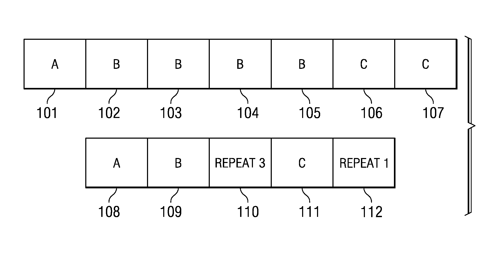
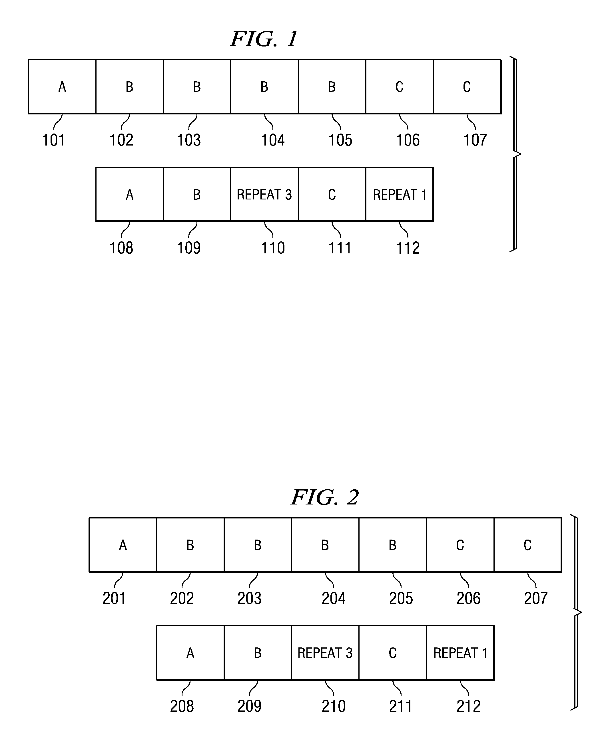
[0045] The trace recording format accommodates compression of consecutive trace words. When at least two consecutive trace words are the same value, the words 2 through n are replaced with a command and count that communicates how many times the word was repeated. The maximum storage for a burst of 2 through n words is two words as shown in FIG. 1, where word 101 does not repeat, words 102,103,104 and 105 are identical and then words 106 and 107 are identical. This sequence compresses as follows—word 108 is the same as word 101, word 109 has the...


PUM


Abstract

Data from both a positive edge sample and negative edge sample are used to determine a data bit. The primary and secondary clocks capture two copies of the data. A sample is taken with a positive edge of one clock and the negative edge of the other clock each bit period. These two captured data values are combined along with the data value captured by the previous negative edge to determine the data bit value. The captured data may be dynamically de-skewed previous to being clocked into a buffer based on the clock edges sampling the data.

Description

BACKGROUND OF THE INVENTION [0001] During applications code development, the development team traverses a repetitive development cycle shown below hundreds if not thousands of times: [0002] 1. Building code—compile and link a version of applications code [0003] 2. Loading code—loading the code into real hardware system or a software model [0004] 3. Debugging / Profiling code—chasing correctness or performance problems [0005] 4. Making changes—making source code edits, or changing the linker directives [0006] The load and change portions of this cycle are generally viewed as non-productive time, as one is either waiting for code to download from the host to the target system or looking through files that need changes and making changes with a text editor. [0007] Any trip through the loop can either introduce or eliminate bugs. When bugs are introduced, the development context changes to debug. When sufficient bugs are eliminated, the development context may change to profiling. There a...

Claims


Application Information

Patent Timeline
Patent Type & Authority Applications(United States)
IPC IPC(8): G06F11/00
CPCG06F11/3648G06F11/3636
Inventor SWOBODA, GARY L.
Owner TEXAS INSTR INC
Why Eureka
Try Eureka