Filtration device

a filtration device and filtering technology, applied in the field of filtration devices, can solve the problems of large portion where membranes are provided, difficult to provide membranes in high density, and blockage of membranes, and achieve the effects of improving filtration performance, high density, and efficient separation and removal

Inactive Publication Date: 2006-11-23
MAEZAWA IND +1
View PDF4 Cites 10 Cited by
  • Summary
  • Abstract
  • Description
  • Claims
  • Application Information

AI Technical Summary

Benefits of technology

[0012] According to the filtration device of the present invention, the vibration occurring during the time when bubbles jetted from a diffusion tube rise can be transmitted to the entire bundled membrane, and suspension components deposited on membrane surfaces or between membranes can be efficiently separated and removed. Further, since the diffuser tube is formed from tube bodies having a small diameter capable of threading into between the hollow fiber membranes for insertion, not much space for disposition is required even if a plurality of diffuser tubes are inserted into a single bundled membrane, so that hollow fiber membranes can be disposed in a high density, thereby allowing the improvement of filtration performance, while achieving the downsizing of the filtration device.

Problems solved by technology

In any case of the water purification and the treatment of highly polluted water, the continuation of filtration treatment by means of a filtration device using a membrane module leads to deposition of suspension components contained in a liquid to be treated on the surface of membranes or between membranes, which becomes the cause of blockage of membranes.
Thus, it was difficult to provide membranes in high density.
Accordingly, the volume of the portion where membranes are provided became large, which led to the upsizing of the filtration device.
Further, there was a problem that, by only performing overall air diffusion from the lower part of the membrane module, only the surface of the hollow fiber membranes was exposed to air diffusion, so that air diffusion to between membranes, particularly to the vicinity of catchment portion where blockage of the membranes progresses became insufficient.
Hei 8-215548 has an air diffusion structure at one end of the membrane module by which air is diffused through air diffusion openings, so that air is only diffused to the outer surface of the hollow fiber membrane, but not to the inner surface thereof, which was not considered to be sufficient in terms of cleaning efficiency.
In addition, there was a problem that the device was not applied to a membrane module in which a multiplicity of hollow fiber membranes are arranged in a bundle in a round shape.
Hei 7-61420 merely has a structure in which a plurality of porous pipes are mixed into the bundle of hollow fibers in which a multiplicity of hollow fiber filtration membranes are arranged in a round shape, which caused a problem of insufficient air diffusion to between membranes.
In either case, when the number of hollow fiber membranes constituting a membrane module becomes large, the cleaning efficiency becomes worsened.
Therefore, there was a limitation for the number of hollow fiber membranes constituting a membrane module, and accordingly there was also a limitation for the improvement of filtration efficiency.

Method used


Image

  • Filtration device
  • Filtration device
  • Filtration device

Examples


Embodiment Construction

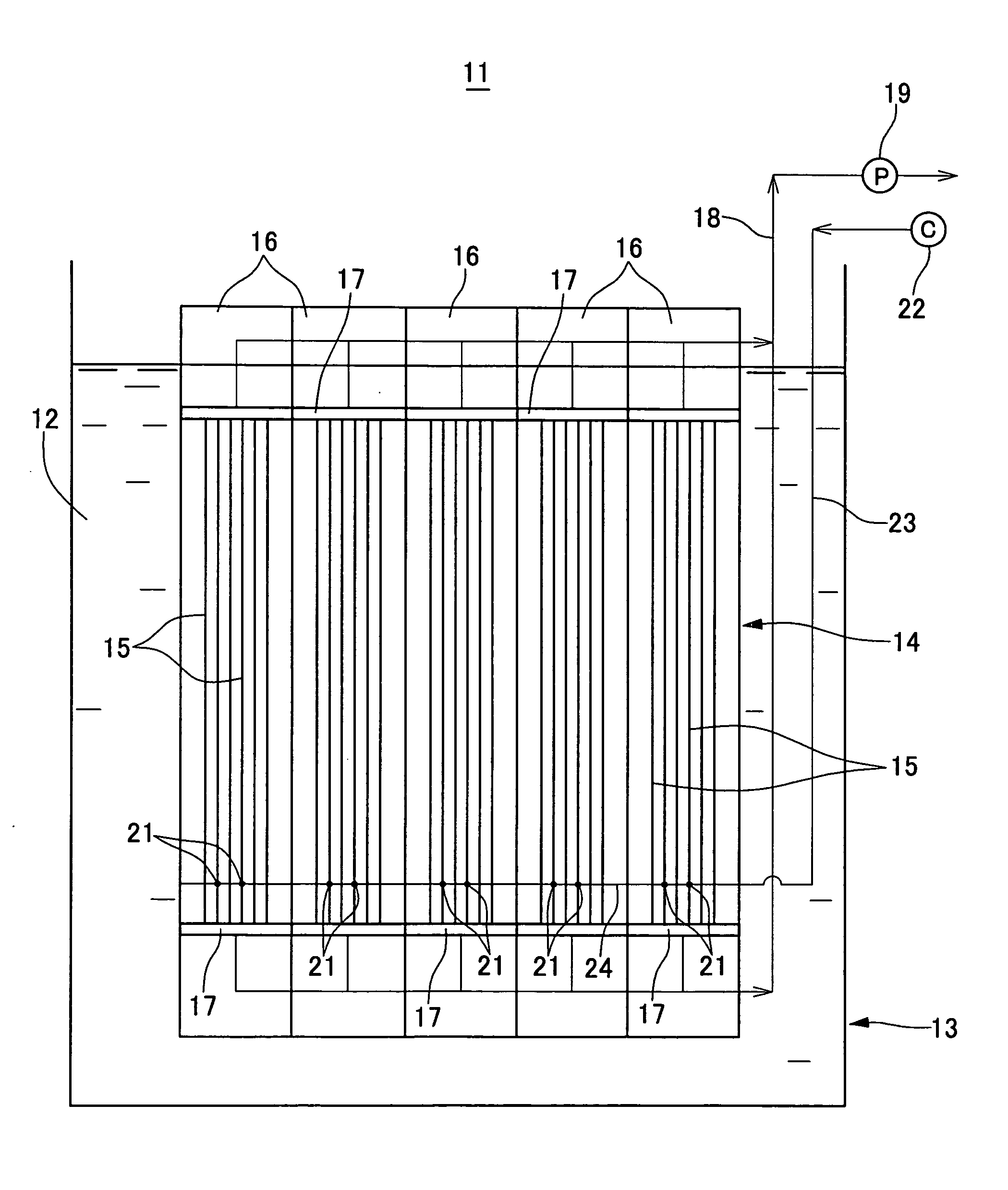
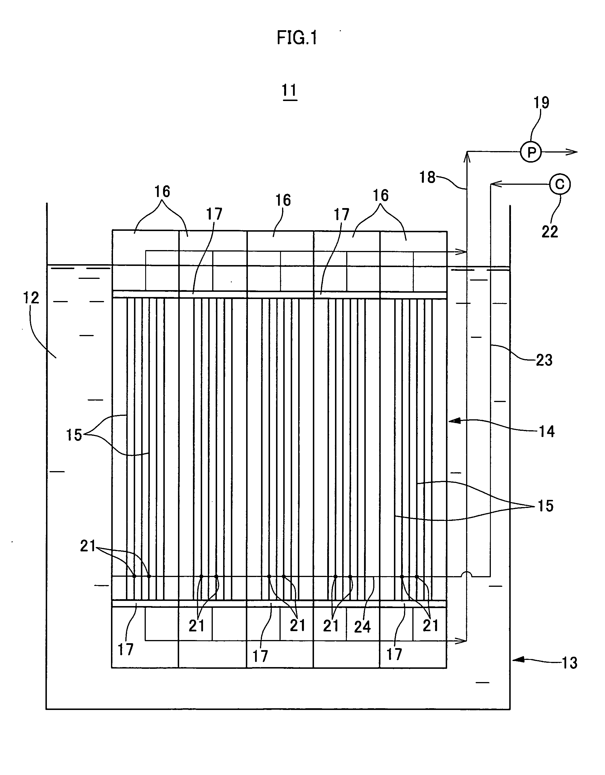
[0016] The filtration device of the present invention will be described in more detail based on FIGS. 1 to 3 which show one embodiment in which the device is applied to an immersion type suction filtration device. Reference numbers used in FIGS. 1 to 3 are as follows:

[0017]11 . . . Filtration device; 12 . . . Liquid to be treated; 13 . . . Immersion tank; 14 . . . Membrane module; 15 . . . Hollow fiber membrane; 16 . . . Bundled membrane; 17 . . . Catchment portion; 18 . . . Treated liquid discharge tube; 19 . . . pump; 21 . . . Diffuser tube; 22 . . . Air compressor; 23 . . . Air induction tube; 24 . . . Header; 25 . . . Diffuser opening

[0018] In the filtration device 11 shown in the present embodiment, a membrane module 14 is disposed in an immersed manner in an immersion tank 13 filled with a liquid to be treated 12 which was introduced. The membrane module 14 is formed from the combination of ten bundled membranes 16 aligned in two rows each having five, in each of which a mul...


PUM


Abstract

There is provided a compact filtration device capable of efficiently separate and remove suspension components adhered to membrane surfaces or to between membranes by allowing bubbling action by means of bubbles from an air diffusion tube to effectively affect the entire hollow fiber membrane, and capable of disposing inside hollow fiber membranes in high density. In a filtration device 11 for performing solid-liquid separation by allowing a liquid to be treated 12 containing suspension components to permeate a membrane module 14 for immersion type suction filtration or external pressure filtration, said membrane module 14 is formed from bundled membranes 16 in which a multiplicity of hollow fiber membranes 15 with their axes being in the vertical direction are contacted closely with each other at the upper and lower ends thereof, and a diffuser tube 21 is threaded into between said multiplicity of hollow fiber membranes 15 for insertion at the lower part of the bundled membrane 16.

Description

TECHNICAL FIELD [0001] The present invention relates to a filtration device, more particularly to a filtration device which performs solid-liquid separation by allowing a liquid to be treated containing suspension components to permeate a membrane module, and especially to a filtration device provided with an air diffuser which performs air bubbling with bubbles from a diffuser tube. BACKGROUND ART [0002] Membrane modules as a catchment portion in which a plurality of hollow fiber membranes are disposed in a bundled manner with its one end or both ends fixed to a fixed member in an open state are used being attached to an immersion type suction filtration device or an external pressure type filtration device. Conventionally, membrane modules have been widely used in a field of what is called microfiltration such as purification of river water or lake water. Recently, not limited to the field of water purification, much consideration has been given to the application thereof for the ...

Claims


Application Information

Patent Timeline
Patent Type & Authority Applications(United States)
IPC IPC(8): B01D65/02
CPCB01D61/20B01D63/02B01D2315/06B01D2321/185B01D2313/26B01D65/08B01D63/04C02F3/20
Inventor SUZUKI, TATSUHIKOMORITA, TOORUIDA, KIYOSHI
Owner MAEZAWA IND
Why Eureka
Try Eureka