Feedback influenced increased-quality-factor scanning probe microscope

a scanning probe microscope and feedback influence technology, applied in the field of imaging, can solve the problems of affecting the rate at which force signals drift, affecting the accuracy of scanning probes, etc., and achieve the effect of reducing the shear force applied

Inactive Publication Date: 2006-11-23
WARREN ODEN L +2
View PDF3 Cites 9 Cited by
  • Summary
  • Abstract
  • Description
  • Claims
  • Application Information

AI Technical Summary

Benefits of technology

[0011] a controller in communication with said sensor and said scanner, said controller including a sensor feedback circuit receiving said displacement signals and an AC setpoint signal, said AC setpoint signal having a frequency generally equal to the frequency at the peak of the displacement versus frequency curve of said sensor, the output of said sensor feedback circuit being applied to said sensor to oscillate the same, said controller further providing output to said scanner in response to said displacement signals to control the separation distance between said sensor and said sample.
[0015] a controller in communication with said sensor and said scanner, said controller including a sensor feedback circuit receiving said displacement signals and an AC setpoint signal, said AC setpoint signal having a frequency generally equal to the frequency at the peak of the displacement versus frequency curve of said sensor, the output of said sensor feedback circuit being applied to said sensor to oscillate said member, said controller further providing output to said scanner in response to said displacement signals to control the separation distance between said sensor and said sample.
[0021] The present invention provides advantages in that soft samples can be imaged on a microscopic level using a highly damped sensor while reducing the shear forces applied to the sample as the sample is scanned.

Problems solved by technology

Unfortunately, problems exist in that soft samples are often damaged by the plowing action of the tip on the sample as the sample is rastered by the piezoelectric scanner in the x-y plane.
Feedback attempts to inhibit the common plate of the displacement sensor from actually deflecting which leads to rapid restabilization of the displacement sensor after hard collisions with pronounced surface features.
However, this places considerable demands on the rate at which force signals drift since it is often necessary to image a large field of view at a slow lateral scan.
A slow drift in the attractive force direction results in a slight increase in the contact force applied to the sample over the scan.

Method used


Image

  • Feedback influenced increased-quality-factor scanning probe microscope
  • Feedback influenced increased-quality-factor scanning probe microscope
  • Feedback influenced increased-quality-factor scanning probe microscope

Examples


Embodiment Construction

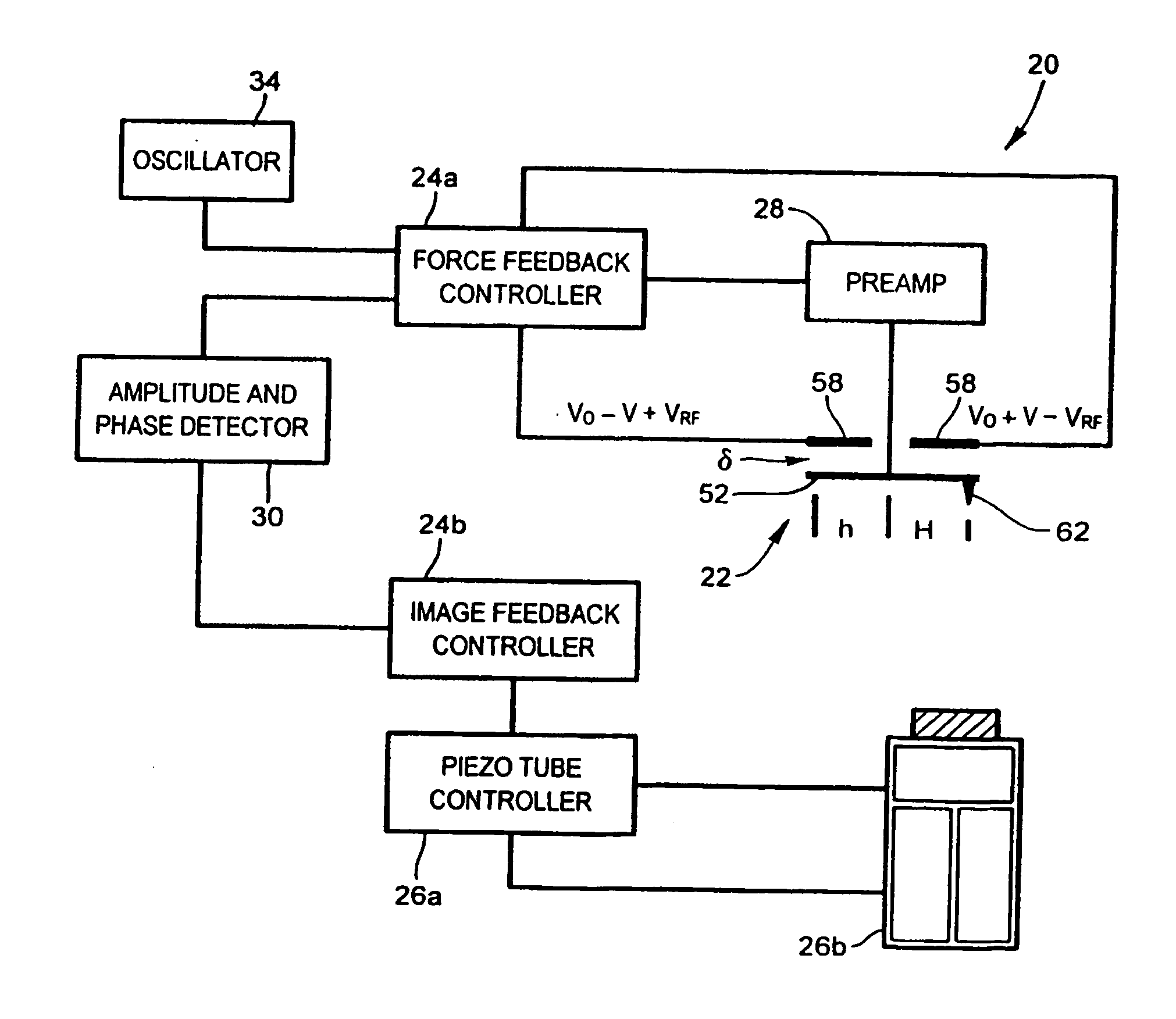
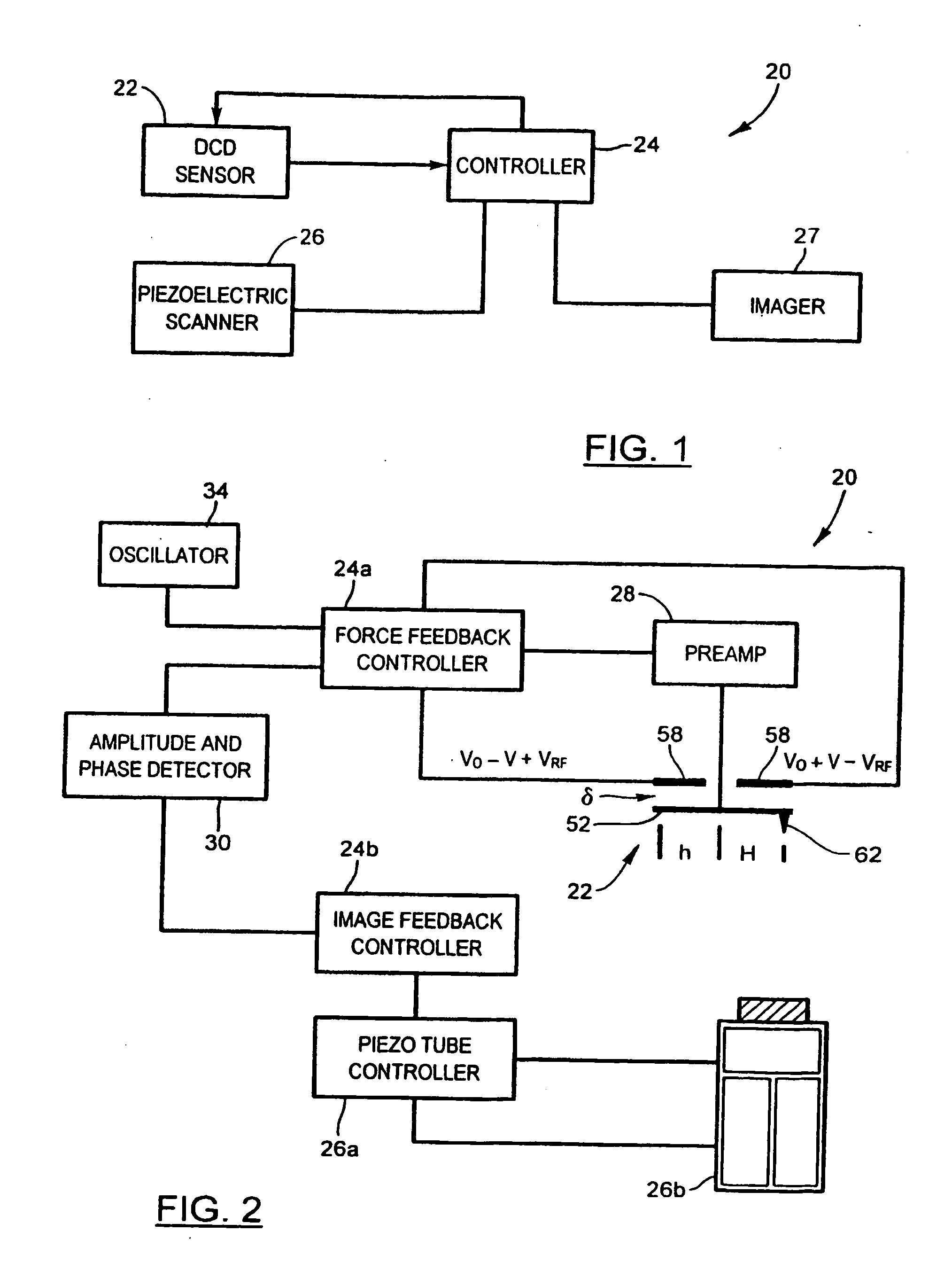
[0035] Referring now to FIG. 1, an interfacial force microscope (IFM) under force-feedback control and configured to operate in an intermittent contact mode to generate microscopic images of a sample under observation in accordance with the present invention is shown and is generally indicated to by reference numeral 20. As can be seen, the IFM 20 includes a differential-capacitance displacement (DCD) sensor 22 to contact intermittently the sample to be imaged. A controller 24 is coupled to the DCD sensor 22 as well as to a piezoelectric scanner 26 positioned adjacent the DCD sensor 22 and supporting the sample. The piezoelectric scanner 26 is responsive to the controller 24 to move the sample in a vertical direction to alter the sensor-sample separation. The piezoelectric scanner 26 is also actuable to move the sample laterally in an x-y plane to raster the DCD sensor 22 over the sample at a rate equal to about 2 to 3 μm / s. An imager 27 such as a NanoScope IIIa MultiMode manufactur...


PUM


Abstract

An interfacial force microscope includes a differential-capacitance displacement sensor having a tip mounted on an oscillating member. The sensor generates displacement signals in response to oscillations of the member. A scanner is adjacent the sensor and supports a sample to be imaged. The scanner is actuable to move the sample relative to the sensor to bring the tip into intermittent contact with said sample as the member oscillates. A controller is in communication with the sensor and the scanner. The controller includes a sensor feedback circuit receiving the displacement signals and an AC setpoint signal. The AC setpoint signal has a frequency generally equal to the frequency at the peak of the displacement versus frequency curve of the sensor. The output of the sensor feedback circuit is applied to the sensor to oscillate the member. The controller also provides output to the scanner in response to the displacement signals to control the separation distance between the sensor and the sample.

Description

FIELD OF THE INVENTION [0001] The present invention relates generally to imaging and in particular to a method and apparatus for intermittent contact imaging. BACKGROUND OF THE INVENTION [0002] Atomic-force microscopy has become widely used to image surfaces of samples on a microscopic scale. Its popularity to a large extent is due to the fact that an atomic-force microscope (AFM) measures the force or force gradient between a sharp tip disposed on a cantilever and a sample surface at a picoNewton (pN) level as opposed to the tunneling current measured with a scanning tunneling microscope (STM). This of course allows the AFM to image insulating as well as conducting samples. [0003] AFMs can be operated in either contact or intermittent contact modes. When operating in a contact mode, the deflection of a weak cantilever is kept constant while servoing the vertical extension of a piezoelectric scanner supporting the sample being imaged. The piezoelectric scanner is also rastered in an...

Claims


Application Information

Patent Timeline
Patent Type & Authority Applications(United States)
IPC IPC(8): H01J3/14H01J5/16G01B7/34G01Q10/06G01Q20/00G01Q60/34
CPCB82Y35/00G01Q10/065G01Q60/34
Inventor WARREN, ODEN L.NORTON, PETER R.GRAHAM, JOHN F.
Owner WARREN ODEN L
Why Eureka
Try Eureka