
Process for producing dental prosthesis and kit for use for therein

a technology for which is applied in the field of manufacturing dental prostheses and kits, can solve the problems of limited use of single crowns, no mechanical strength and tenacity of alumina nor spinel, etc., and achieve excellent beauty, high fluidity, and excellent beauty.

Inactive Publication Date: 2006-11-23
NORITAKE CO LTD
View PDF10 Cites 20 Cited by
  • Summary
  • Abstract
  • Description
  • Claims
  • Application Information

AI Technical Summary

Benefits of technology

[0020] According to the manufacturing method of the first invention, in the formation of the at least two coating layers constituting the armored portion, the cast coating layer is superposed, by casting, on at least a part of the surface of the back coating layer serving as a backing. In this instance, since the viscosity of the second porcelain (forming the cast coating layer) at the casting temperature is lower than that of the first porcelain (forming the back coating layer), movement of the back coating layer is advantageously restrained.
[0021] That is, since the viscosity of the first porcelain upon casting of the second porcelain is higher than that of the second porcelain, fluidity of the first porcelain is lower than that of the second porcelain. Therefore, since the first porcelain is not likely to be influenced by flow of the second porcelain at high temperature upon casting of the second porcelain, the second porcelain having the higher fluidity is poured into a space (i.e., the above-described void portion) which has a desired configuration and which is located between the casting mold and the back coating layer, before movement of the first porcelain. As a result of this, the first porcelain, i.e., the previously formed back coating layer is restrained from being moved in a direction of flow of the second porcelain that is poured posteriorly.
[0022] Therefore, according to the manufacturing method of the first invention, it is possible to manufacture, by a casting process, a dental prosthesis having an armored portion which is constituted by at least two coating layers (i.e., ornament layers) and which has an excellent beauty. Further, by mounting another porcelain, as needed, it is possible to obtain a dental prosthesis (e.g., artificial crown) which has an excellent beauty and which is still closer to an natural tooth.
[0023] According to the kit of the second invention, since the kit includes the first material for preparing the above-described first porcelain and the second material for preparing the second porcelain whose viscosity at the predetermined casting temperature is lower than that of the first porcelain, the manufacturing method of the first invention can be easily practiced. That is, it is possible to manufacture, by a casting process, a dental prosthesis having an armored portion which is constituted by at least two coating layers (i.e., ornament layers) and which has an excellent beauty.
[0024] According to the manufacturing method of the third invention, in the first step as one of the steps of forming the ceramic layers for manufacturing the dental prosthesis, the first ceramic layer of the first composition is fixedly formed on the surface of the frame made of zirconia. After that, in the second step, the second ceramic layer of the second composition is fixedly formed on the first ceramic layer, such that the first ceramic layer is covered with the second ceramic layer. Since the first and second ceramic layers have the above-described first and second compositions, respectively, both of the ceramic layers have substantially the same coefficient of thermal expansion as that of the frame made of zirconia, it is possible to restrain occurrence of crack in the frame or ceramic layers (i.e., armored portion) due to difference in coefficient of thermal expansion, in a cooling process of heat treatment for fixedly forming the ceramic layers, thereby enabling the dental prosthesis to be manufactured without occurrence of crack in the zirconia frame and ceramic layers. It is noted that the first ceramic layer may be formed to cover an entirety of the surface of the frame, or formed such that a part of the surface of the frame is exposed without being covered with the first ceramic layer. The phrase “the first ceramic layer is covered at its surface” is interpreted to encompass not only a case where the first ceramic layer is completely covered, but also a case where the first ceramic layer is covered partially at its surface.
[0025] Particularly, where the viscosity of the first ceramic layer (previously formed on the lower side) is higher that that of the second ceramic layer (posteriorly formed on the upper side) at the same temperature, it is possible to restrain the previously formed first ceramic layer from being softened to flow or deform when the second ceramic layer is fixedly formed. It is therefore possible to manufacture the dental prosthesis, with the desired thickness of the first ceramic layer as a lower layer of the two ceramic layers being maintained.

Problems solved by technology

However, since the ceramic prosthesis constituted in its entirety by the crystallized glass whose mechanical strength and tenacity are relatively low, it can not be used for a bridge or the like required to have a strength, and accordingly its use is limited to a single crown.
However, neither alumina nor spinel has a mechanical strength and tenacity that are high enough to be used as a bridge.

Method used


Image

  • Process for producing dental prosthesis and kit for use for therein
  • Process for producing dental prosthesis and kit for use for therein
  • Process for producing dental prosthesis and kit for use for therein

Examples


example 1

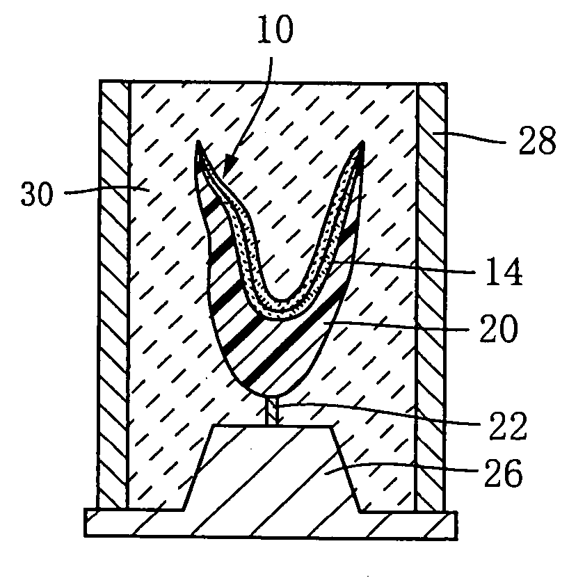
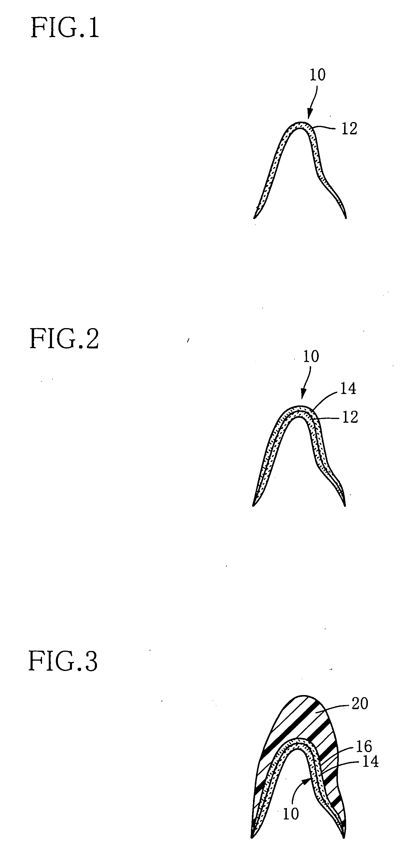
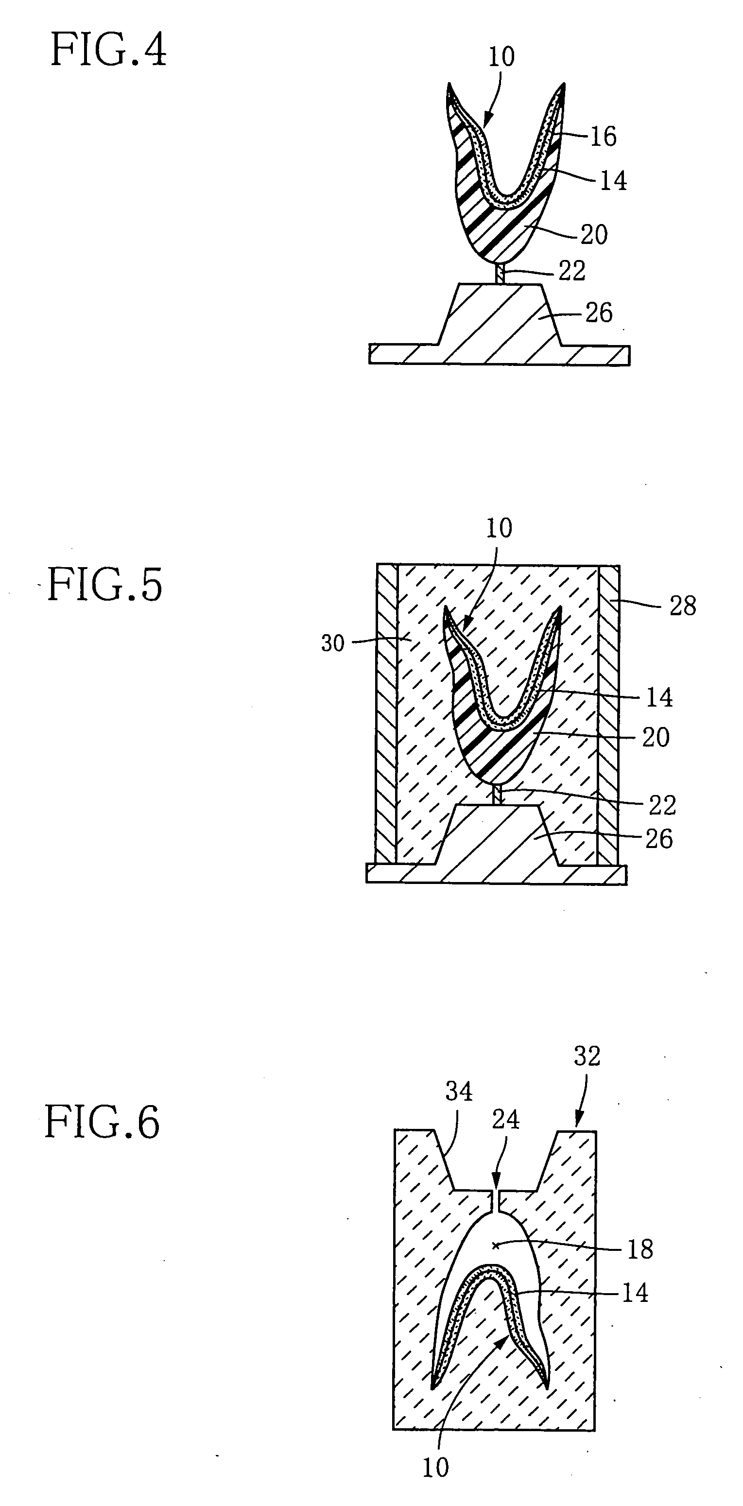
[0131]FIGS. 1-7 are schematic views for explaining a method of manufacturing a dental crown 38 as an example of a dental prosthesis according to an example of the first and second inventions. The crown 38 is to be mounted, for example, as a front tooth of an upper jaw of an adult. The present invention is applicable also to all other teeth. In FIG. 1, the frame 10 made of zirconia (single crown frame) produced separately is prepared. This frame 10 made of zirconia is produced by conventionally known means, for example, forming a denture mold with plaster and pouring the zirconia into the denture mold.

[0132] First, a first porcelain was uniformly applied (mounted) with a brush, onto a surface 12 of the above-described frame 10 made of the zirconia, such that the first porcelain had a thickness of about 0.1 (mm). The first porcelain used herein is slurry including ceramic powders of composition indicated in Table 1 given below and prepared by mixing 100 mass parts of propyleneglycol-...

examples 2-10

[0142] In each of these examples, a dental crown having the same configuration as Example 1 was manufactured in the same manner as in Example 1, except that the second porcelain in the form of ceramic powders having composition indicated in Table 2 was used and that viscosity of the second porcelain at the casting temperature was as indicated in Table 2. It is noted that “VISCOSITY” in Table 2 indicates a value at the casting temperature.

TABLE 2VISCOSITYNo.SiO2Al2O3K2ONa2OLi2OB2O3CaOCeO2MgOSb2O3ZrO2(cP)264.315.89.95.90.30.11.00.71.01.0—4.5 × 106362.617.89.74.90.31.01.00.71.01.0—5.0 × 106463.915.89.94.90.31.01.00.71.01.00.55.3 × 106564.716.010.05.00.31.01.0—1.01.0—5.4 × 106664.316.210.64.80.20.81.20.80.11.0—6.3 × 106765.415.210.54.80.40.81.00.80.11.0—6.4 × 106866.716.09.04.50.31.01.5—1.01.0—7.2 × 106966.015.910.04.50.10.80.70.80.21.0—7.5 × 1061066.616.49.24.10.10.80.50.80.51.0—8.5 × 10⁶

(Indicating composition of second porcelain used in each Example: (mass %))

[0143] As is apparent...

example 11

[0145] In this Example, a frame made of a metal was used as the substrate. The metal frame is constituted by 78 (mass %) of Au, 7.1 (mass %) of Pt, 9.8 (mass %) of Pd, 2.4 (mass %) of Ag and inevitable impurity.

[0146] Further, in this Example, a back coating layer was formed in the same manner as in Example 1, except that the first porcelain used herein included ceramic powders of composition indicated in Table 3 in place of the composition indicated in Table 1 and that a burning temperature of the back coating layer was 980 (° C.).

TABLE 3FIRSTSECONDPORCELAINPORCELAINMATERIALSiO247.764.5COMPOSITIONAl2O314.014.3(Mass %)K2O10.010.0Na2O6.09.0Li2O0.30.3ZrO2—0.5CaO1.01.0MgO1.00.4SnO220.0—VISCOSITY1.5 × 107 (cP)1 × 10⁷ (cP)AT CASTINGTEMPERATURE

[0147] Subsequently, a cast coating layer was formed in the same manner as in Example 1, except that the second porcelain used herein included ceramic powders of composition indicated in Table 3 in place of the ceramic powders of the composition ...


PUM

PropertyMeasurementUnit
Temperatureaaaaaaaaaa
Percent by massaaaaaaaaaa

Abstract

A method of manufacturing a dental prosthesis, including: (a) a step of preparing a substrate of the dental prosthesis that is constituted by a dental molding material; (b) a step of forming a back coating layer on at least a part of a surface of the substrate, by using a first porcelain that is constituted principally by ceramic; (c) a step of forming a casting mold such that the substrate is disposed in the casting mold and such that a void is provided on a surface of the back coating layer; and (d) a step of forming a cast coating layer on at least a part of a surface of the back coating layer, by pouring a second porcelain into the void at a casting temperature. The second porcelain is constituted principally by ceramic whose composition is different from that of the ceramic of the first porcelain that viscosity of the second porcelain at the casting temperature is lower than that of the first porcelain. Also disclosed are a kit and a dental porcelain set that are used for manufacturing the dental prosthesis.

Description

TECHNICAL FIELD [0001] The present invention relates to a method of manufacturing a dental prosthesis, and a kit (i.e., dental porcelain set) that is preferably used for the same. BACKGROUND ART [0002] A dental prosthesis used in an oral cavity needs to have a strength bearing a strong biting strength, and is also required to have a beauty for having an appearance equivalent to that of a natural tooth. For this reason, conventionally, there is manufactured a dental prosthesis including: a substrate (i.e., a body portion serving as a base (core) of the prosthesis) such as a frame having high strength; and an armored portion formed on the substrate, for providing a color tone similar to that of a natural tooth, or a transparency. As this kind of dental prosthesis, there are some described in Patent Documents 1 and 2, for example. As means for forming the armored portion on the substrate, there is widely used a method of mounting a malaxation of powders of porcelain (i.e., dental ceram...

Claims


Application Information

Patent Timeline
IPC IPC(8): A61C13/00B05D3/00A61L33/00A61C5/08A61C5/70A61C5/73A61C5/77A61C13/09A61C13/20
CPCA61C5/08A61C5/10A61C13/20A61C13/09A61C13/0003A61C5/70A61C5/77A61C13/00A61C13/08A61C13/083A61C13/081
Inventor SAGO, SUMIHITOSAKAKIBARA, TOSHIOHIRATA, TATSUHIKOMATSUMOTO, ATSUSHI
Owner NORITAKE CO LTD
Learn More