Real-time electronic spray deposition sensor

a real-time electronic and sensor technology, applied in the field of electronic spray deposition sensors, can solve the problems of inability to always provide information on the spatial distribution of deposition, time-consuming and laborious, and chemical analysis can be costly and subject to errors, so as to improve the indication of uniformity and spray effectiveness, reduce field time, and improve data processing efficiency

Inactive Publication Date: 2006-11-23
RGT UNIV OF CALIFORNIA
View PDF28 Cites 9 Cited by
  • Summary
  • Abstract
  • Description
  • Claims
  • Application Information

AI Technical Summary

Benefits of technology

[0018] A spray deposition measurement tool is disclosed having novel electrical sensor processing and monitoring to improve indication of uniformity and spray effectiveness, via real-time data, and therefore require less field time and allow more efficient data processing.

Problems solved by technology

This technique requires the placement, collection, scanning and post processing of stains on cards, and is time consuming and labor intensive.
These chemical analyses can be costly and subject to errors from contamination and recovery problems.
Moreover, they cannot always provide information on spatial distribution of deposition, droplet deposition density or the fraction of target area covered by the deposit.
The process is a tedious, meticulous and time-consuming task.
An additional limitation of these techniques is that they do not provide real-time measurements.

Method used


Image

  • Real-time electronic spray deposition sensor
  • Real-time electronic spray deposition sensor
  • Real-time electronic spray deposition sensor

Examples


Embodiment Construction

[0061] Referring more specifically to the drawings, for illustrative purposes the present invention is embodied in the apparatus generally shown in FIG. 1 through FIG. 14. It will be appreciated that the apparatus may vary as to configuration and as to details of the parts, and that the method may vary as to the specific steps and sequence, without departing from the basic concepts as disclosed herein.

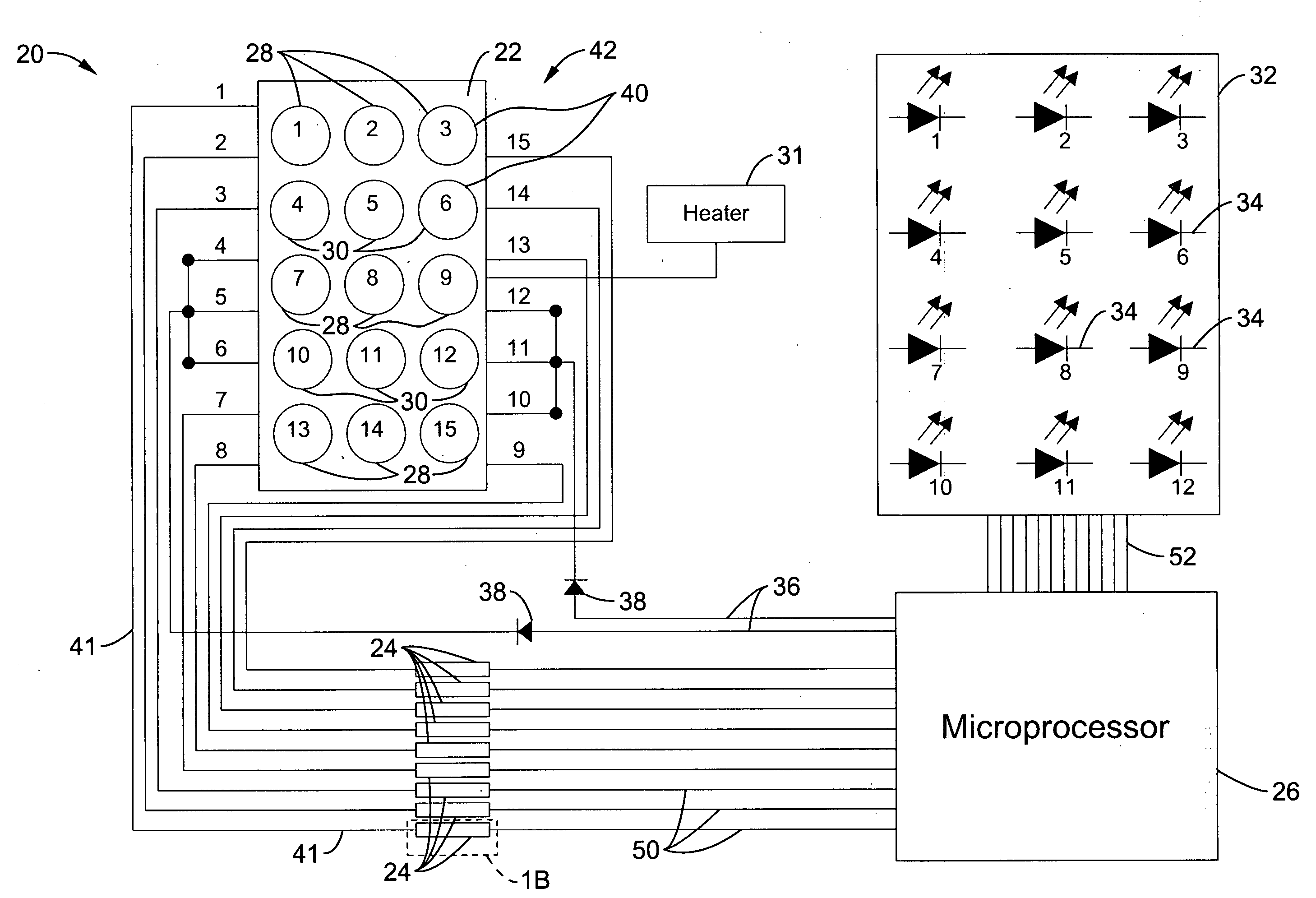
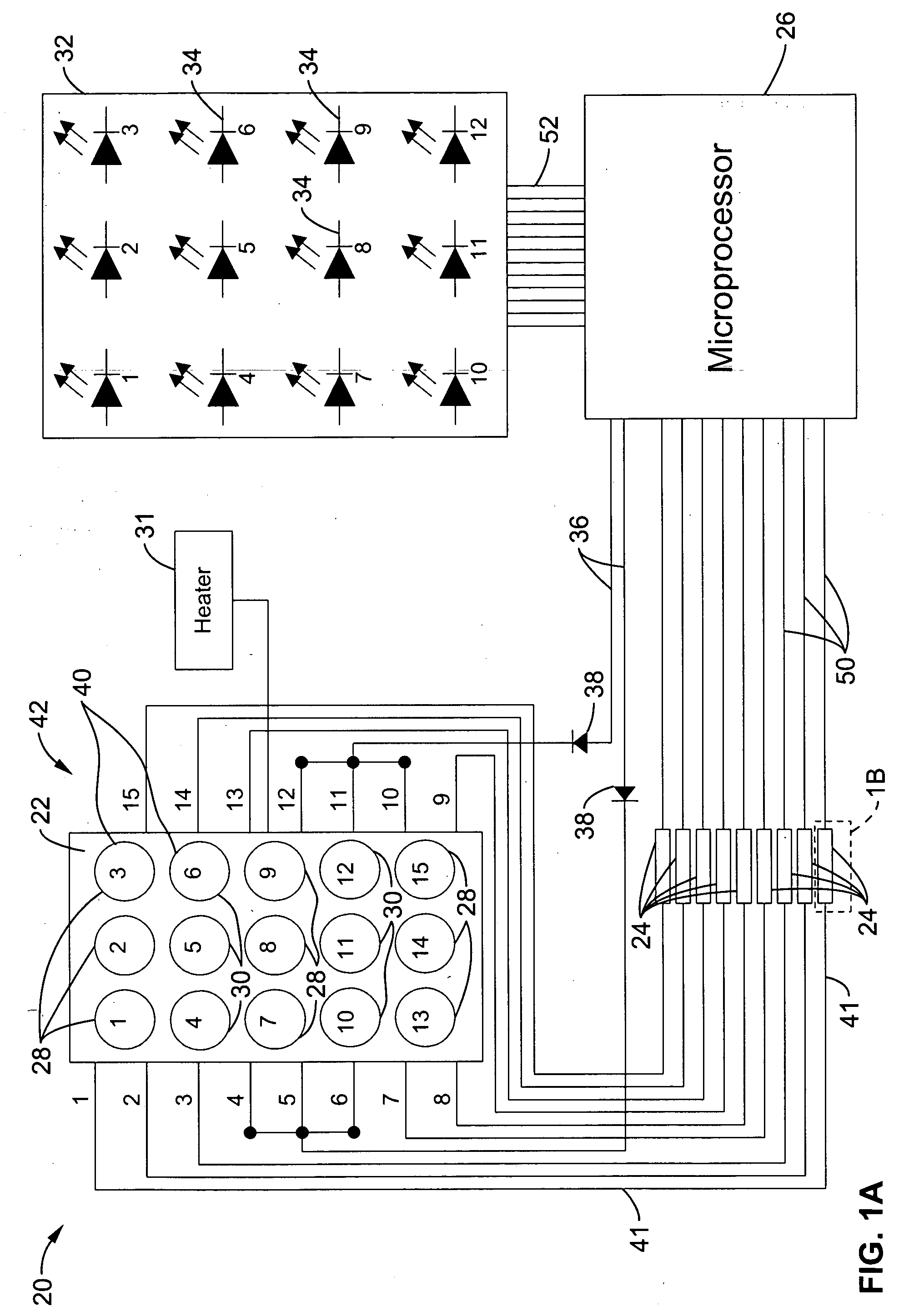
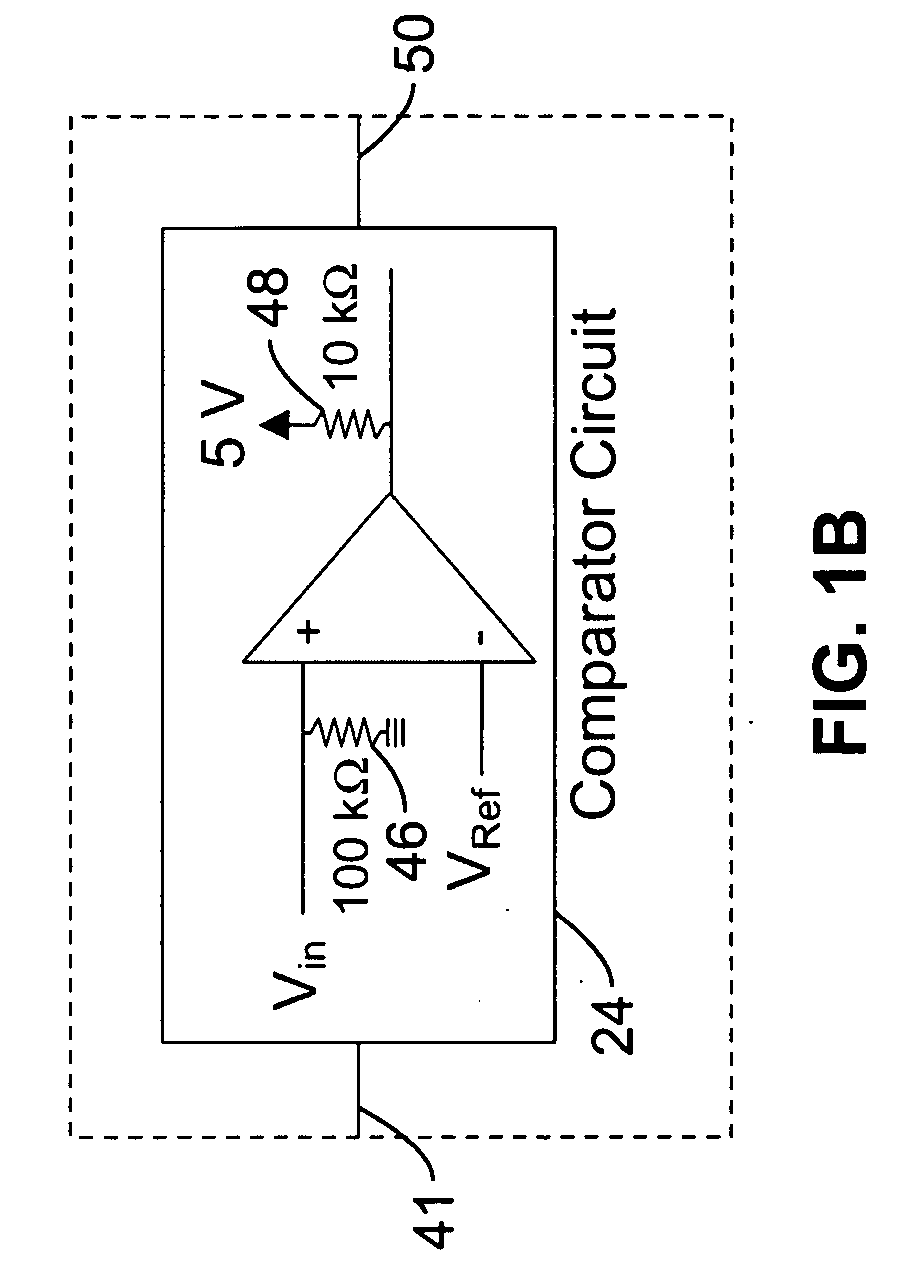
[0062] Referring to FIG. 1, the electronic spray sensory system 20 of the present invention comprises a sensor surface 22, comparator circuit 24, microprocessor 26 and display 32. The sensor surface 22 was constructed by filling 15 holes 40, of an electronic prototyping board 42, with single-sided solder pads, with electrical solder. As would be appreciated by one skilled in the art, the sensor surface 22 may be constructed from a variety of means to generate an array, such as an etched silicon wafer. As illustrated in FIG. 1, a 5 row×3 column pattern was selected as the array pattern...


PUM


Abstract

An electronic spray deposition sensor for sensing deposition of liquid on an exterior surface is disclosed. The deposition sensor has a sensing surface comprising a plurality of electrically conductive elements disposed across the sensing surface. The conductive elements are closely spaced apart from each other and insulated from each other on the sensing surface. A comparator circuit is coupled to the conductive elements to detect the presence of liquid at the conductive element. In particular, conductive elements are disposed in an array across the sensing surface such that the presence and location of the liquid on the sensing surface may be determined.

Description

STATEMENT REGARDING FEDERALLY SPONSORED RESEARCH OR DEVELOPMENT [0001] This invention was made with Government support under Grant No. EB002138, awarded by National Institutes of Health. The Government has certain rights in this invention.CROSS-REFERENCE TO RELATED APPLICATIONS [0002] Not Applicable INCORPORATION-BY-REFERENCE OF MATERIAL SUBMITTED ON A COMPACT DISC [0003] Not Applicable NOTICE OF MATERIAL SUBJECT TO COPYRIGHT PROTECTION [0004] A portion of the material in this patent document is subject to copyright protection under the copyright laws of the United States and of other countries. The owner of the copyright rights has no objection to the facsimile reproduction by anyone of the patent document or the patent disclosure, as it appears in the United States Patent and Trademark Office publicly available file or records, but otherwise reserves all copyright rights whatsoever. The copyright owner does not hereby waive any of its rights to have this patent document maintained...

Claims


Application Information

Patent Timeline
Patent Type & Authority Applications(United States)
IPC IPC(8): G08B21/00
CPCG08B21/12Y10T137/189
Inventor GILES, D. KENCROWE, TREVER
Owner RGT UNIV OF CALIFORNIA
Why Eureka
Try Eureka